BBC BROWN BOVERI SK 55

GENERAL DESCRIPTION


A New 500 kW Short-Wave Transmitter

photo BBC Brown Boveri SK 55 
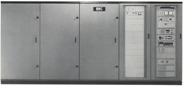
A newly developed 500 kW short-wave transmitter is the latest addition to BBC's family of modern short-wave and medium-wave transmitters with ratings from 100 to 300 kW. The most notable features of the new transmitter are:

This new 500 kW short-wave transmitter keeps up the Brown Boveri tradition by setting new standards of efficiency, design and technology in this power class.

RF STAGES

Extensive computer calculations and trial runs on models provided some interesting technical solutions with respect to the best circuit layout for the entire short-wave range and also with regard to determining the optimum operating point.

Preliminary Stages

The preliminary stages up to the driver tube are fully transistorized and function as a broadband amplifier. The oscillator controls a programmable regulating stage, which ensures that the r.f. final-stage tube is driven properly at each operating frequency. The driver stage is equipped with a modern, condensed-vapour cooled BBC triode of type CTL 12-1, which has a high amplification factor. This amplifier tube operates in grounded-grid circuit. The broadband matching network is initially adjusted for each broadcasting band. Fine adjustment of the driver stage grid-circuit components is unnecessary due to the circuit layout chosen.

Final Stage

The r.f. final stage has a newly developed high-power tetrode of type CQK 650-1 from Brown Boveri. The tetrode is operated without grid current and delivers the rated power. A Pi-circuit, which is tuned to the set transmission frequency, matches the driver anode to the control grid of the r.f. final-stage tube. The output capacitance of the Pi-circuit is represented by the input capacitance of the r.f. final-stage tube, so that resonance sources on the grid side are eliminated. Power is coupled out over a cylindrical capacitor arranged around the anode of the r.f. final-stage tube. The result is an extremely compact design with low inductances in the leads and a homogeneous distribution of the current in the tube. The tube is easily accessible and simple to replace.

The output circuit consists of three Pi-elements, which transform the 50 ohms terminating impedance to the desired anode impedance. In the standard version, the transmitter can be tuned continuously in the broadcasting bands from 5.9 MHz to 26.1 MHz. By changing the capacitances, the frequency range can be extended down to 3.9 MHz. The series inductances are designed as tunable loops. By making the inductances of the loops low, the frequencies of any unwanted resonances lie far above the operating frequency. All stray inductances of the incoming leads act as components of the loop and therefore do not constitute additional sources of interference resonances. The first shunt capacitor lies parallel to the r.f. final-stage tube and is disconnected at the higher transmitter frequencies.

Compensation of the voltage standing wave ratio (VSWR) is achieved by adjusting the capacitor and the loop at the output. Possible antenna mismatch is therefore compensated for by the Pi-element closest to the output. Consequently, the currents and voltages in the rest of the anode network are the same as those during rated operation. Water is used to cool the loops and variable vacuum capacitors.

AUDIO-FREQUENCY STAGES

There is a choice between two types of modulation amplifier from BBC: the push-pull class B modulator with two amplifier tubes of type CQK 200-3 in the final-stage of the modulator and the new PSM switching amplifier (PSM = Pulse Step Modulator). Outstanding features of the PSM switching amplifier are:

Dynamic carrier control (DCC) is possible with both modulators. The object of DCC is dynamic reduction of the carrier power as a function of the modulation peaks, and therefore also reduction of the input power.

Push-Pull Class B Modulator

The a.f. final stage is equipped with two power tetrodes of type CQK 200-3. These two amplifier tubes operate without grid current, so that a transistorized voltage amplifier suffices as the driver stage. The quiescent currents of the tetrodes can be set to low values since special correcting networks improve the linearity. The efficiency achieved in program service is therefore substantially higher than with conventional modulators.

The anode voltage is led to the two modulator tubes via the mid-point of the modulation transformer's primary winding. The r.f. final-stage tubes receive the anode voltage from the modulation choke. A varistor connected in parallel with the secondary winding of the modulation transformer, protects the r.f. final-stage tube against overvoltage.

PSM Amplifier

The PSM amplifier delivers output voltages between 0 and 28 kV, corresponding to the program signals, and has an output rating which varies between 0 and 2800 kW. The mean d.c. component and the a.c. modulation component can be set separately. The amplifier can therefore be used with a reduced power output (e.g. for local supply).

The PSM amplifier consists of approximately 40 switching stages, the outputs of which are connected in series. The number of stages to be connected depends upon the instantaneous value of the voltage to be amplified. Half of the switching stages deliver the carrier value, an appropriate number being switched on and off for higher or lower voltages, respectively.

The 40 switching stages are fed by 40 d.c. power supplies from the mains, via a three-phase isolating transformer with one primary and 40 separate secondary windings. The secondary voltages are rectified and smoothed in an intermediate d.c. circuit. There is therefore a separate d.c. voltage source for each switching stage. Switch-on or switch-off of each individual stage is controlled via an optical-fibre cable. When the semiconductor valve is 'turned on', the corresponding voltage source is connected in series with the sources below it; when the valve is 'turned off', a bypass is created for the current. High-speed thyristors act as switching valves in this system.

TRANSMITTER CONTROL SYSTEM

The hinged frame contains the control equipment and monitoring instruments, and, from top to bottom, the r.f. frequency oscillator, reflectometer, measuring equipment, motor control system, frequency selector, operating unit with display lamps, logic, power supply and bridge memory. The key- switch in the operating unit can be turned to select manual, automatic or remote control of the switching sequences.

TUNING

The r.f. stages are tuned via the frequency selector subassembly and the motor control unit. When the key is in the position 'Manual', all of the variable capacitors and loops required for a frequency change can be set via the motor control unit by pressing the relevant buttons. The actual position is shown on a digital display. The automatic tuning system is activated by turning the key to 'Automatic'. Automatic tuning takes place in two steps, beginning with the operator pressing a button to transfer the desired transmission frequency from one of the 100 freely programmable memories in the frequency selector subassembly to the automatic transmitter tuning system. The r.f. oscillator immediately changes to the new transmitter frequency. Using the bridge memories, all tunable elements are then set to the selected broadcasting band. During the slow run-up of the anode voltage, phase and load discriminators monitor the fine tuning.

COOLING

All of the tubes used, such as the CTK 12-1, CQK 650-1 and, in the case of the push-pull class B modulator, the two CQK 200-3 tubes, are cooled by condensed vapour. Loops, their tuning contacts and variable vacuum-type capacitors are cooled by the same cooling water. The heat dissipated by the cooling circuit can be either used in the building's heating system or led to water/water or water/air heat-exchangers. A high-pressure fan is incorporated in the r.f. stage cubicle and in the push-pull class B modulator to cool the terminal heads of the tubes. Additional cooling is also provided by air at low pressure passing through the transmitter cabinets.

SAFETY EQUIPMENT

The safety system for the 500 kW short-wave transmitter complies in full with the recommendations set down in IEC 215-1. The system offers multiple protection. A key-interlock system combined with an earthing switch makes it impossible for doors leading to live equipment to be opened. Each door is also provided with a special contact which is integrated in the interlock circuit. An earthing hook situated behind each door offers additional security.

POWER SUPPLY

The transmitter can be supplied with power from a medium-voltage network rated 3 to 24 kV. A small transformer supplies 3 x 380 V to transmitter auxiliaries such as the cooling and heating systems.

Push-Pull Class B Modulator

The converter transformer is switched and protected by a BBC SF6 circuit-breaker, while built-in overcurrent relays protect the transformer against overload. Protection of the transformer for the auxiliaries is provided by a fuse disconnector. The static converter supplies power to the transmitter via a filter consisting of smoothing choke and capacitors. To protect the power tetrode in the event of disturbance, the value of the high voltage is determined within only a few microseconds and the energy stored in the filter is discharged through a crowbar system.

PSM Ampliflier

The transformers for the transmitter supply and auxiliaries are each protected by a fuse disconnector. The anode circuit-breaker is incorporated after the transformer on the 500 V side. A crowbar system is not required for the PSM switching amplifier. When disturbances occur, the channels are simply blocked within a few microseconds. This is adequate since there is no equipment installed between the switching amplifier and the r.f. stages which could store energy of any consequence.

TYPICAL INSTALLATION IN A BROADCASTING STATION

With the PSM Switching Amplifier

In the standard layout of the 500 kW short-wave transmitter with PSM switching amplifier in a transmitting station, the r.f. cubicle is bolted to the control cubicle and installed in an opening in the wall. Behind it is the PSM switching amplifier. A separate cabinet on the roof of the building contains the low-pressure fan with air filter. A duct connects the cabinet to the transmitter. On the left of the r.f. cubicle space has been provided for a balancing unit. Next to this is the water-cooling unit, comprising the system tank, the water pump, the water recooler and the monitoring instruments. The space required for this layout is only 46 m2.

With the Push-Pull Class B Modulator

In the standard layout of the 500 kW short-wave transmitter with push-pull class B modulator, the r.f. cubicle and the control cubicle are bolted together and installed in an opening in the wall. Behind this, and ensuring sufficient space for maintenance work such as the replacing of tubes, is the modulator cubicle. A high-voltage cell contains the converter and the filter capacitors with the earthing switch. The heavy transformers and chokes are separated by a partition and are accessible from the outside. The high-voltage circuit-breakers and isolators, and also the station transformer, are installed at a central location in the transmitter station.

TECHNICAL SPECIFICATIONS
Power output 500 kW
Operating mode A3
Carrier frequency range - standard: 5.9 to 26.1 MHz
- with accessory: 3.9 to 26.1 MHz
Output impedance 50 ohms, unbalanced
- with balun: 200 ohms/300 ohms, balanced
Permitted VSWR 1:1.7
Time to change frequency Average approx. 20 s, max. 60 s
Harmonics Complies with International Telecommunication Union (ITU) Radio Regulation, Edition 1982 Appendix 8, Regulation 1982
AF frequency range - PSM modulator: 50 Hz to 7.5 kHz
- Push-pull class B modulator: 50 Hz to 10 kHz
AF qualities Complies with international standards
Mains connection 3 ph/3 kV to 24 kV
Mains frequency 50 or 60 Hz
Overall efficiency in program service - with PSM modulator: >70%
- with push-pull class B modulator: >65%
Power factor >0.9
Permitted ambient temperature - standard: 1°C to 45°C
- with air-flap accessory: -20°C to +45°C
Required floor space - with PSM modulator: Approx. 46 m2
- with push-pull class B modulator: Approx. 65 m2
Specifications may change without notice

TUBE COMPLEMENT
RF stages AF stages and modulator
Number Type Number Type
1 CQK 650-1 2 CQK 200-3
1 CTK 12-1


THIS TYPE OF TRANSMITTER IS INSTALLED IN THE FOLLOWING COUNTRIES

ITU Country
ITU Country
flag BIH BIH BOSNIA-HERCEGOVINA flag FIN FIN FINLAND
flag D D GERMANY flag IND IND INDIA
flag IRN IRN IRAN flag IRQ IRQ IRAQ
flag JOR JOR JORDAN flag KWT KWT KUWAIT
flag LBY LBY LIBYA flag NIG NIG NIGERIA
flag S S SWEDEN flag SUI SUI SWITZERLAND
flag TUR TUR TURKEY flag UAE UAE UNITED ARAB EMIRATES
flag USA USA USA flag CVA CVA VATICAN CITY