COLLINS 821A-1

GENERAL DESCRIPTION


photo Collins 821A-1 
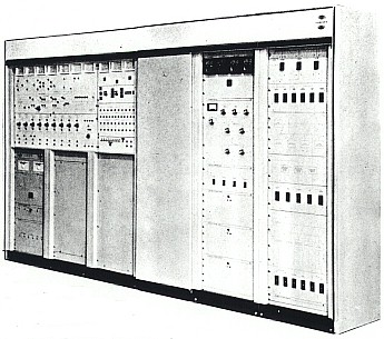
The new 821A-1 250 kw transmitter is Collins Radio Company's latest addition to the high-power HF broadcast product line. With totally new and unique design features, this high frequency transmitter advances present day techniques of super-power transmitter design.

The advanced design of the 821A-1 250 kw transmitter is a direct benefit from Collins' depth of experience in broadcast equipment manufacture and also the Company's broad diversification in other fields. Drawing from related technologies in areas of communication, computation and control, Collins Radio Company adapted and applied these techniques to the manufacture of high frequency broadcast equipment to produce an advanced transmitter design with superior performance and greater reliability.

Features such as the 20 second tuning, the Diagnostic Control Panel, remote operation, and simplified but highly efficient circuitry ... plus unique as well as conventional protective devices, set the 821A-1 transmitter apart from previous transmitters of high power design.

20 SECOND TUNING OF THE 821A-1 TRANSMITTER

The tuning techniques of the Collins 821A-1 250 kw transmitter are unique. A fully automatic tuning system enables broadcasters to change frequencies in the 3.95 to 26.5 Mc/s range in a maximum of 20 seconds in contrast to as long as 10 to 15 minutes needed for the conventional HF transmitter. If an average of four frequency changes are made a day, the Collins 821A-1 can save as much as an hour of "on-air" time by eliminating "down-time" during frequency changes.

Automatic tuning also permits an operator with little previous experience to rechannel or operate the transmitter. Changing frequency is fast, easy and simple.

First the operator sets the desired carrier frequency on the coarse position control head. Then he selects either of the two internal crystal oscillators, or either of two external sources. If an internal oscillator is used, he selects the proper crystal which presets the transmitter for a frequency change.

A change may be made by pushing the "Tune Start" button. In less than 20 seconds, the 821A-1 is tuned to the new frequency and ready for programming ... accomplished during normal "station-break" periods. This fast automatic process can be initiated from either the Diagnostic Control Panel or the operator's remote console.

Built-in safety precautions prevent overload and damage to the transmitter throughout the automatic tuning process. The efficiency of the tuning process in the 821A-1 250 kw transmitter surpasses anything available to high frequency broadcasters in the past.

The 821A-1 is of the greatest utility when operated in its automatic mode. However, the transmitter is equipped for semi-automatic tuning from the Diagnostic Control Panel for operator control of the tuning elements in the driver and PA output networks. Calibrated indicators permit presetting of the tuning elements in accordance with a prelogged tuning program. Touch-up adjustments of the controls can be accomplished by monitonng the respective plate currents or discriminator outputs on the control panel. All transmitter protective devices remain operative during operator tuning.

THE DIAGNOSTIC CONTROL PANEL

The Diagnostic Control Panel is a centralized unit where local control and operation of 821A-1 circuits are performed. It provides the operator with a convenient visual display of the entire system from the RF oscillator, the audio inputs, throughout the transmitter, including the automatic tuning. In case of an abnormal condition, the control center alerts the operator to the problem and localizes the area requiring attention. In this way, the operator is assisted by the Diagnostic Control Panel in fault-finding which saves time by simplifying the search for trouble areas.

Illuminated light displays are used extensively to provide rapid monitoring of important functions. Seventy indicator lights, operating on reduced voltage for longer life, notify the operator of functions such as warning, fault and operational status of the transmitter.

Simplified schematic diagrams of the transmitter's RF, audio, servo and automatic tune control subsystems are displayed on the Diagnostic Control Panel. Metering information is selected by push-buttons located on the block diagram of the circuit in question.

The metering signals are normalized to a decimal equivalent and are presented on test meters located at the top of the Diagnostic Control Panel. The normal value for each voltage or current is printed next to each push-button. This unique metering presentation results in rapid localization of trouble or fault.

REMOTE OPERATION

The 821A-1 is normally operated remotely using the controls located on the operator's console. Remote operation permits locating the console up to 150 feet from the transmitter. Auxiliary terminal equipment is available to permit complete long distance extension of the functions appearing on the operator's console by cable. The remote console controls are duplicated at the Diagnostic Control Panel.

The remote operator's console contains meters and controls necessary for monitoring of electrical parameters and important functions. Filament and plate power control, selection of frequencies, initiation of automatic tune cycles and selection of high or low power are controllable by switches located on the console panel. The presence of warning or a fault condition in the transmitter is indicated by an alarm circuit. An amber indicator light signifies a warning condition and a red light indicates a fault.

OPERATING ECONOMY AND HIGH RELIABILITY

Large coaxial transmission line sections provide "inductive" elements which are resonated by vacuum variable capacitors. The large current-carrying surfaces make possible losses as low as 3% using enough tuned sections to achieve at least 80 db of harmonic attenuation. In addition to reduced power losses, higher reliability is achieved due to reduced heating and lower power required from RF and modulator tubes. Use of high-gain power tetrode tubes eliminates the usual high power driver stages. Use of silicon rectifiers and generous safety margins in design of power components further aid overall reliability.

COMPACTNESS AND EASE OF INSTALLATION OF THE 821A-1 TRANSMITTER

The basic transmitter system is divided into three separate sections. They are: the high voltage vault, the high voltage enclosure containing the RF and modulator sections, and the control center. The entire system occupies only 800 sq. ft. The 821A-1 is a 250 kw transmitter designed to fit into yesterday's 50 kw transmitter space. Collins' three-section design, coupled with remote capability, offers great flexibility for installation. No floor ducts are required; all interconnecting wiring is in overhead cable trays. This results in a lower construction cost than with transmitters requiring floor ducts and multi-level installation. The Collins 821A-1 250 kw transmitter can be installed in many configurations without remodeling or rebuilding present structures.

SAFETY

Factors for safe-guarding personnel as well as preventing damage to the equipment through carelessness, abuse or misjudgment have been designed into the protective circuitry of the 821A-1 250 kw transmitter.

The high voltage power vault of the 821A-1 transmitter is provided with an oil immersed switch which must be opened prior to personnel entering the area.

Automatic switches are also used to disconnect the 4160-volt primary power line and to ground the high voltage dc input to the transmitter. Thus, the technician is fully protected when making an inspection of the high voltage power supply.

The low voltage power supplies of the 208-volt ac primary power and control circuits can be separated from the high voltage enclosures. This is an important safety feature allowing initial checkout and future maintenance of the circuits without having to bypass high voltage circuit interlocks not involved in the checkout procedure.

A unique device to protect expensive components in the 821A-1 is an effective and fast-acting "crowbar" circuit designed to short high voltage circuitry and remove high voltage and primary power in the event of even slight arcing.

HIGH EFFICIENCY TANK CIRCUITS

Tank circuits in the 821A-1 250 kw transmitter are of an advanced design and have proved superior to anything previously used in high power transmitters. The design of the output tank circuit and harmonic filter eliminates the conventional switched or variable coils, which are often troublesome. The output tank circuit employs resonated coaxial line sections utilizing vacuum variable capacitors for the servo driven automatic tuning and loading functions. Excessive concentration of current in the line is avoided, resulting in losses as low as three per cent yet providing excellent harmonic reduction with trouble-free performance.

By meeting demanding requirements of quality and reliability in developing products for broadcast communications, Collins Radio Company has earned a solid reputation as leader in the broadcast industry. High performance of Collins equipment is proven in installations throughout the Free World. Additional factors for consideration in selecting Collins Radio Company's 821A-1 250 kw HF transmitter are:

For more detailed and technical information on the Collins 821A-1, call or write the Regional Office nearest you.

TECHNICAL SPECIFICATIONS
ELECTRICAL SPECIFICATIONS
Emission High-level amplitude modulation (A3); frequency shift keying (F1)
Frequency Range 3.95 to 26.5 Mc/s, continuous coverage
Frequency Control By oven controlled crystal oscillator (two furnished) or by either of two customer furnished external signal sources
Frequency stability with Type CR-27/U Crystals From +5 to +50°C and primary voltage variation ±10%, less than 5 parts per million frequency change per 24-hour period. Greater stabilities obtainable with higher stability crystals.
Tuning Time Frequency change accomplished in 20 seconds or less
Tuning Mode Automatic - with operator override capability
Power Output At least 250-kw unmodulated carrier power, 100% sine wave or trapezoidal modulation
Carrier Shift Less than 5%, exclusive of that caused by primary power regulations
Output Impedance 300 ohms, balanced (75 ohms unbalanced output available)
Allowable VSWR 1.5:1 maximum
Type of Modulation High level AM, FSK
Modulation Capability Capable of 100% sine wave or sine wave clipped 9 db. Less than 5% tilt or overshoot for clipped waveform at 100% modulation
Modulation Duty Factor Continuous at 100% sine wave; 5 minutes at 9 db clipped sine wave
Audio Input for 100% Modulation +10 dbm ±2 db
Audio Input Impedance 600/150 ohm, balanced or unbalanced
Audio Response Within 1 db from that at 1000 cps between 100 and 7500 cps and within 2 db between 50 to 10,000 cps, at all modulation levels up to 95%
Audio Distortion Not more than 4% distortion when modulated 95% over the frequency range of 100 to 5000 cps; and not more than 5% from 50 to 100 cps and from 5000 to 7500 cps
Noise Level Carrier hum and extraneous noise is at least 50 db (unweighted) below 100% modulation
Harmonic and Spurious All harmonics and harmonically related spurious emissions are at least 80 db below carrier level. Incidental phase modulation products that occur close to the carrier in the output of the transmitter are at least 43 db below 1 radian
Power Input At rated carrier output; 475 kw at .95 power factor. At 100% sine wave; 710 kw at .95 power factor
Power Source 4160 volts ±3%; 50 ±3 cps; 3 phase, 3-wire, standard (60 ±3 cps and other voltages optional)
ENVIRONMENTAL SPECIFICATIONS
Altitude 0 to 6000 feet
Temperature Operating: Standard Inside Ambient: +5° to +50°C at sea level, +5° to +38°C at 6000 feet altitude
Storage: -35° to +60°C
Humidity 0 to 95% relative humidity
MECHANICAL SPECIFICATIONS
Size Not over 800 square feet, over-all; 13 feet minimum floor-to-ceiling height
High Voltage Power Supply 400 square feet
High Voltage Enclosure 250 square feet
Operational Area 150 square feet
Transmitter Weight 48,925 pounds

TUBE COMPLEMENT
RF stages AF stages and modulator Rectifiers
Number Type Number Type Number Type
2 4CV100,000C 2 4CV100,000C

1 4CX3000A 2 4CX3000A

1 4CX350A 2 7788

2 8233 2 2N2147


2 2N657


THIS TYPE OF TRANSMITTER IS INSTALLED IN THE FOLLOWING COUNTRIES

ITU Country
ITU Country
flag USA USA USA