HITACHI KOKUSAI ELECTRIC TA-1002

GENERAL DESCRIPTION


100 kW SHORTWAVE BROADCASTING TRANSMITTER TYPE TA-1002

The TA-1002 100KW shortwave transmitter is a computer-controlled, high-performance equipment for the international broadcast band of 5.9 to 21.9 MHz.
The TA-1002's prime design considerations are placed on long-term durability for frequent frequency change which are inevitable requirements for shortwave overseas broadcasting services. This design object has been achieved by introducing the latest electronic devices and digital technique combined with KOKUSAI's years of experience in manufacture and maintenance.
Simple design and thorough design review of r.f. component location plan have been sought out for achieving maintainability in the smallest transmitter housing and for reduced frequency change time.

photo Hitachi Kokusai Electric TA-1002 * 
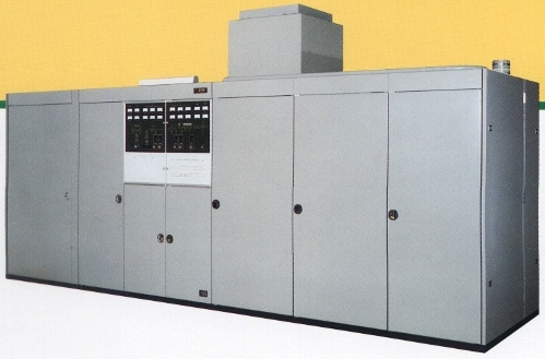
Centralized Display System

* Complete Protection and Safety Measures

* Computer-Controlled Automatic Tuning and Retuning

* Simplified Frequency Change Mechanism

* Highly Stabe R.F. Sourse

* Slideless Variable Coil

* Durable Coil Contacts

* Water-cooled R.F. Coils

* Water-cooled High Power Variable Vacuum Capacitors

* R.F. Component Ideally Located on "Monolith" Copper

* "Hyper-Vapotron" Tetrodes Used

* Multistage LPF Configulation r.f. output circuit

* Simple and Stable Modulation System

* Built-in Water Purifying System

* Compact Outdoor Radiator

* Dual-stage Starter for High-Voltage Supply

* High Reliability Coaxial Switching Assembly

* Enclosed type Coaxial Dummy Load

* Computer-Controlled Command and Supervisory Console

FEATURE 1

Centralized display system providing sufficient operational information
Centralized monitor system and a mimic diagram display are combined to facilitate visual observation of the transmitter operating status: push button switches for power on/off, channel selection and antenna exchanger are self-illuminated type, capable of flashing until the control action is completed.
When LOCAL/REMOTE switch is placed in the REMOTE position, all the control functions including frequency selection are remotely controlled.

Complete protection and safety measures
The protective devices include an alarm for load SWR degradation, an overcurrent alarm and an overheating alarm.
Major safety devices are a crowbar circuit which can instantly discharge the high voltage of condensers, dual door system for the r.f. section which not only assures operator's safety but also improves shielding effect, viewing windows in the inside doors for visual observation of transmitter operation. High voltage access doors are provided with interlock switches, high voltage grounding switches and high voltage discharge rods.

Computer-controlled automatic tuning, retuning
The precision digital servo devices for tuning the r.f. driver and final stages are centrally controlled by a microcomputer.
The transmitter thus performs automatic tuning for a new frequencv and automatic retuning for changeable load conditions. The transmitter can always be matched to its load optimumly.

Simplified frequency change mechanism
Earlier stages up to predriver are series of solid state broadband configulations, thereby reducing the number of tuning elements or frequency change.

Highly stable r.f. source
R.f. carrier fraquencies are generated by a highly stable digital synthesizer. Any 100 frequencies can be preset in 100 Hz steps in the international broadcast bend.

FEATURE 2

Slideless variable coil
In case of frequency change, the computer-controlled servo system drives the contact assembly of the main tuning coil to pull apart from the coil surface. After being moved to the set position, the servo system pulls the contact assembly back to the coil surface to be complete contact condition and gets ready for operation. By this unique, excellent mechanism, avoiding the useless sliding action, long-term stable and trouble free operation is surely promissed.

Durable coil contacts
All the r.f. coils conisting the transmitter's output circuit are of continuously variable type. Switchgears which have possibilities to induce arcing/sparking, are not used in the output circuit.
The contacts used are made of special solid silver alloy and are designed to be fully durable against long-term, severly conditioned operation.

Water-cooled r.f. coils
To avoid temperature rising which has a bad influence on the contacts, coils of the r.f. output circuit are water-cooled.
This water-cooling contributes greatly to the stable operation.

Effectively cooled high power variable vacuum capacitors
High power rated, effectively cooled variable vacuum capacitors are used as making pair of the variable coils. No switchgear is used.

RF components ideally located on "Monolith" copper
The final r.f. tube, tank circuit, harmonic filter etc. are located closely with each other on a single copper-plate shelf for eliminating earth potential differences. This leads to reduction of circuit loss and of spurious emission due to unwanted resonance.

FEATURE 3

"Hyper-Vapotron" tetrodes used
Because of their largest plate dissipation currently available per unit area, "Hyper-Vapotron" tetrode tubes (closed circuit, recirculated vapor-cooling) are operated in the final r.f. stage (TH555) and the final a.f. stage (TH581 x 2) at conservative rating with a relatively low anode voltage applied. This has achieved a high reliability design in the smallest cabinet housing.

FEATURE 4

Multistage LPF configulation r.f. output circiut
With continuously variable coils and capacitors,the r.f. output circuit forms a multistage low pass filter. Optimumly tuned this multistage filter suppresses spurious radiations as much as possible. TVI or other communication interference are extremely reduced to a negligible order.

Simple and stable modulation system
Modulation is simultaneously applied to the plate and screen grid of the final tube only, which is the most simple and proven stable modulation system. The final stage modulator is a class-B push-pull amplifier using two power tetrodes. The earlier stages are of solid-state, modular design.

FEATURE 5

Built-in water purifying system
A water purifying system is built in the transmitter cabinet for cooling of high power components such as power tetrodes, variable vacuum capacitors, r.f. coils etc.

Compact outdoor radiator
After cooling high power components such as power tetrodes etc., heat of circulating pure water is transfered to secondary cooling water via built-in heat exchanger and is effectively dissipated by a compact outdoor-type radiator.

Dual-stage starter for high-voltage supply
At the input side of the high voltage supply, a dual stage starter consisting of two vacuum contactors and series resistors is adopted, thus effectively limiting rush current at the time of power on.

FEATURE 6

High reliability coaxial switching assembly
As a switching device of the transmitter output feeder, rugged and highly reliable, rotary contact type coaxial switching assembly can be supplied at a customer's option.
This switching assembly may be set through a remote control as an element of the automated transmitting system.

Enclosed type coaxial dummy load
For the test operation of the transmitter, completely enclosed type coaxial dummy load can be supplied at a customer's option. Heat dissipation device making pair of the dummy load is of outdoor installation type.
In combination with the coaxial switch assembly, transmitting operation with antenna or test operation of the transmitter can easily be selected either locally or through a remote control.

Computer-controlled command and supervisory console
For commanding and supervision of whole broadcasting system including setting of broadcast program, on/off switching of the transmitters, changing-over of the output feeder routes, control console can be supplied as an optional base. The console is fully controlled by high speed computers and displays the operating status of the transmitting system. Hard copy printout is also available.
Setting up the unattended transmitting system can fully be realized by this command and supervisory console.

TECHNICAL SPECIFICATIONS
Carrier power output 100 kW +5,-10%
Type of emission A3E (DSB)
Frequency range 5.9 to 21.9 MHz
Covering the international broadcast band in 100 Hz steps
Number of preset frequencies 100 frequencies, maximum
Frequency Stability 2 x 10⁻⁸/day
Frequency change time 20 sec. average
Output impedance 50 ohms unbalanced
Suitable coaxial Copper tube feeder WX-152D (6-1/8 in) or its equivalent
Permissible standing wave ratio Less than 2.0 VSWR
Spurious radiation Below 45 MHz: Less than 25 mW
Above 45 MHz: Less than 10 mW
Audio signal input 150 to 3500 Hz, 0 dBm into 600 ohms
Modulation linearity Linear up to 95% modulation with 100 Hz
Audio frequency distortion Less than 3% up to 80% modulation.
Less than 5% up to 95% modulation.
Signal-to-noise ratio Better than 55 dB at rated output with 1000 Hz 80% modulation
Mains supply (1) 200 V AC 3-phase, 60 kVA
(2) 6600 V AC 3-phase, 240 kVA ave.
Total power factor, better than 90%
Please state mains data in enquiries
Weight 5000 kg (transmitter body only)
Specifications may change without notice

TUBE COMPLEMENT
RF stages AF stages and modulator
Number Type Number Type
1 TH555 2 TH581


THIS TYPE OF TRANSMITTER IS INSTALLED IN THE FOLLOWING COUNTRIES

ITU Country
ITU Country
flag J J JAPAN