| GENERAL DESCRIPTION |
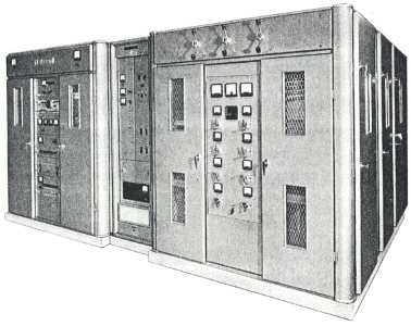 THE B 6123 transmitter embodies techniques designed to provide a small economical high-power h.f transmitter, requiring a minimum of operating personnel. The transmitter, designed to take advantage of 'trapezoidal' modulation, uses vapourcooled valves in the modulated and final r.f stages.
| TECHNICAL SPECIFICATIONS | |||
| Power output | 100 kW carrier at nominal mains voltage | ||
| Frequency range | Broadcast bands between 3200 and 26,100 kc/s as defined by ITU regulations, Geneva, 1959 | ||
| Frequency stability | Better than 5 parts in 106 per month (with B 6104) | ||
| Output impedance | 300 ohm unbalanced (max. v.s.w.r 2:1) | ||
| Drive input | 5 W at radiated frequency | ||
| Frequency response | ±1 dB between 50 and 5000 c/s, ±1.5 dB between 30 and 10,000 c/s, reference 400 c/s, measured at 75% modulation | ||
| A.F harmonic distortion | Over range 50 to 10,000 c/s, less than 2.5% at 50% modulation, less than 4% at 9% modulation | ||
| Noise and residual modulation | At least 56 dB (unweighted) below level corresponding to 100% modulation by sine-wave signal at 1000 c/s | ||
| Power supply | Main h.t rectifier supply adapted to client's requirements. Auxiliary circuits require: 380-440 V (+6% to -10%), 50 c/s (or 60 c/s to order) (±4%) a.c three phase, four wire | ||
| Overall power factor | Better than 0.95 | ||
| Overall power consumption Output (kW) Low band Input (kW) Efficiency (%) High band Input (kW) Efficiency (%) |
Carrier 100 172 58.1 182 55 |
40% sine wave modulation 107 200 53.5 213 50.2 |
95% trapezoidal modulation 156 290 53.8 310 50.4 |
| Dimensions | Transmitter Width 16 ft 9 in. (510.6 cm) Depth 12 ft (366 cm) Transformer enclosure (outdoor if required) Width 14 ft (427 cm) Depth 12 ft (365 cm) |
||
| Specifications may change without notice | |||
| TUBE COMPLEMENT | |||
| RF stages | AF stages and modulator | ||
| Number | Type | Number | Type |
| ? | ? | ? | ? |
| THIS TYPE OF TRANSMITTER IS INSTALLED IN THE FOLLOWING COUNTRIES | |||||
| ITU | Country | ITU | Country | ||
| GRC | GREECE | MLA | MALAYSIA | ||
| SNG | SINGAPORE | ||||