| GENERAL DESCRIPTION |
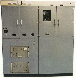 Short Wave Broadcasting Transmitter Type RIZ OR 10 K-06 is a standard amplitude modulated transmitter, designed for operation within SW broadcasting bands between 3,2 and 22 MHz with carrier power of 10 kW.
| TECHNICAL SPECIFICATIONS | |
| OPERATING CONDITIONS | |
| Power Supply | |
| Mains voltage | 3 x 380 V / 220 V, +5%, -10% |
| Power input (fm=1kHz/m=1) | 40 kVA |
| Mains frequency | 50 Hz ±2 Hz |
| Power factor | cos phi greater than 0.9 |
| Modulator Input | |
| Input impedance (from 60 to 10000 Hz) | nominal 600 Ohms balanced |
| Input level (for fm=1 kHz, m=1) (0 dBm=0,775 V across 600 Ohms) |
-4 to +10 dBm |
| Transmitter Output | |
| RF output load impedance | 50 Ohms unbalanced |
| Permissible VSWR | s less than 2 |
| Climatic Conditions | |
| Temperature in transmitter hall | +5 to +45 C |
| Max. altitude above sea level | 2000 m |
| Relative humidity | less than 90% |
| ELECTRICAL CHARACTERISTICS | |
| RF Output Power | |
| Carrier power in the range 3.2 to 22 MHz | 10 kW |
| RF Exciter | |
| Crystal oscillator with fixed frequency in the range | 3.2 to 22 MHz |
| Frequency precision and stability | 2 x 10⁻⁶ Hz/day |
| Frequency synthesizer | as option |
| Modulation System | |
| Type of modulation | High level amplitude modulation |
| Type of emission | 20 A3 Bandwith limiting filters 4,5 kHz or 5 kHz available as option |
| Modulation Characteristics | |
| The ratio of input to output as function of modulation depth (m=30 ... 80%) does not differ by more than | ±0,5 dB |
| Signal to Noise Ratio | |
| Unweighted | more than 50 dB |
| Weighted | more than 60 dB Reference level m=100% fm=1 kHz, sinusoidal Mains voltage sinusoidal |
| Spurious Emission | |
| Mean power of any spurious emission supplied to the antenna transmission line below the mean power of the fundamental | more than 60 dB |
| Carrier Shift | |
| Carrier shift at m=90% with fm=1 kHz sinusoidal and at a constant mains voltage referred to the unmodulated carrier |
less than 4% |
| Overall Efficiency | |
| Overall efficiency | more than 40% (fm=1kHz, sinusoidal) |
| Specifications may change without notice | |
| TUBE COMPLEMENT | |||
| RF stages | AF stages and modulator | ||
| Number | Type | Number | Type |
| 1 | 4CX15,000A | 2 | 4CX5000A |
| THIS TYPE OF TRANSMITTER IS INSTALLED IN THE FOLLOWING COUNTRIES | |||||
| ITU | Country | ITU | Country | ||