| GENERAL DESCRIPTION |
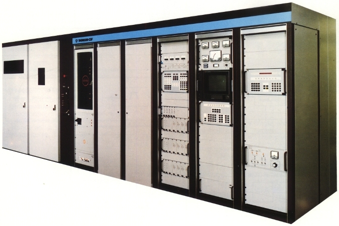 Feature
| TECHNICAL SPECIFICATIONS | |
| R.F. characteristics | |
| Power output (carrier) | 500 kW Reduced power operation DACM operation |
| Frequency range | 5.9 to 26.1 MHz. Extension to 3.9 or 3.2 (optional) |
| Tuning | automatic on any frequency within broadcast bands (and optional on most frequencies outside broadcast bands) |
| Transmission type | A3, A3 with DACM, SSB (optional), AM stereo (optional) |
| Modulation type | digital PDM for anode amplitude modulation |
| Frequency stability | ±2 10-7 per month (or better optional) |
| RF output | 50 ohm unbalanced SWR less than 2 (300 ohm balanced with balun) |
| RF harmonics | better than CCIR specifications (50 mW or less on any frequency) |
| AF characteristics | |
| AF input impedance | more than 5000 ohm balanced between 50 Hz and 7500 Hz, compatible with a 600 ohm balanced line |
| AF nominal level to achieve | 100% modulation at 1000 Hz =0 to +10 dBm adjustable of ± dB by 0.5 dB steps |
| AF band with | 50 Hz to 7500 Hz (or 4500 Hz with a filter) in A3 mode |
| Frequency response | Reference curve stands within the limits below, measured with a 50% modulation rate. For any modulation between 30 and 80%, the curve stands within ±0,5 dB of the reference curve |
| Harmonic distortion | 50 to 100 Hz: 3% at 30 to 80% 100 to 5000 Hz: 2,5% at 30 to 80%, 3% at 90% 5000 to 7500 Hz: 3% at 30 to 80% |
| Noise | Unweighted noise referenced to a 100% modulated carrier with a 100 Hz tone less than 58 dB |
| Modulation capabilities | |
| Maximum modulation factor | 100% from 100 to 5000 Hz 80% anywhere in band |
| Maximum average modulation factor in program operation | 70% (can be sustained continuously) |
| Carrier shift | Less than 5% at 100% modulation with 1000 Hz sine wave |
| Power supply | |
| Three phases 5,5 to 24 kV (or more optionnally) | 1200 kVA |
| Single phase 220 V | 3 kVA permanent |
| Three-phases 220/380 V (can be internally generated) | 50 kVA |
| Overall power efficiency | |
| 70% typically | (64% minimum guaranteed at any modulation on any broadcast band) |
| Environment | |
| Temperature | +1°C to +50°C (extended optionally) |
| Humidity | 95% |
| Altitude | 1500 m (or more optional) |
| Specifications may change without notice | |
| TUBE COMPLEMENT | |||
| RF stages | AF stages and modulator | ||
| Number | Type | Number | Type |
| 1 | TH558 | 1 | TH558 or TH573 |
| 1 | TH562 | ||
| THIS TYPE OF TRANSMITTER IS INSTALLED IN THE FOLLOWING COUNTRIES | |||||
| ITU | Country | ITU | Country | ||
| CTI | COTE D'IVOIRE | F | FRANCE | ||
| GAB | GABON | LBY | LIBYA | ||
| ARS | SAUDI ARABIA | ||||