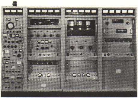
TECHNICAL MATERIEL CORPORATION GPT-40K

GENERAL DESCRIPTION


photo Technical Materiel Corporation GPT-40K PURPOSE OF EQUIPMENT

The GPT-40K Transmitter is a conservatively-rated general purpose transmitter which delivers 40,000 watts PEP (peak envelope power), or 20,000 watts average power throughout the 2- to 28-mc range. The operating modes of the transmitter are:
  1. SSB (single sideband) with suppressed or any degree of carrier.

  2. DSB (double sideband) with suppressed or any degree of carrier. This mode includes AM (amplitude modulation) operation and AME (AM equivalent).

  3. ISB (independent sideband) (separate intelligence on each sideband) with suppressed or any degree of carrier.

  4. FSK (frequency-shift telegraphy).

  5. FAX (Facsimile).

  6. CW (carrier wave) keying (telegraphy).

DESCRIPTION OF EQUIPMENT

  1. GENERAL. - The transmitter consists of an auxiliary frame, a main frame, a PA (power amplifier) frame, and a PS (power supply) frame. All four frames are bolted together and to two base assemblies, two frames per base. The four frames house all the components of the transmitter and are equipped with protective frontdoors. Primary power connections are made through the base assembly. Two antenna bowl assemblies, used for balanced output operation, are located on top of the PS frame. A standard 3-1/8 connector, for unbalanced output operation, is located on top of the PA frame.

  2. AUXILIARY FRAME. - The auxiliary frame houses the exciter components of the transmitter. This frame is identical to the auxiliary frame used in the GPT-10K transmitter.

  3. MAIN FRAME. - The main frame houses a two-stage rf voltage amplifier, the 1-kw IPA, the 10-kw PA and associated power supply and power control circuits. Except for the 10-kw PA (AX-510), the main frame circuits are identical to those in the GPT-10K transmitter. Power Amplifier Section AX-510 replaces the AX-509 used in the 10K transmitter. The physical location of the two power amplifier sections is identical. The only differences existing between them are:

    1. Repositioning of various sub-assemblies to make frames physically compatible.

    2. Replacement of the antenna tuner (in top of PA section, behind meter panel) in the AX-509 with a dummy load in the AX-510.

    3. Electrical output connections.

  4. PA FRAME. - The PA frame houses the 40-kw power amplifier stage of the transmitter. The lower half of the frame is divided into a front and rear section by a partition. The front half houses a filament transformer and removable subassemblies. The rear half houses parts associated with the main power supply and a blower for the power amplifier tube. The upper half of the frame houses the power amplifier tube compartment, associated power amplifier circuit components, and a bandswitch.

    1. PA Frame Meter Panel AM-115. - The PA frame meter panel, located at the top of the PA frame, contains five meters associated with the 40-kw power amplifier. These meters monitor the voltage to the primary of the filament transformer, the rf drive voltage, plate current, rf plate voltage, and output power.

    2. Power Amplifier AX-511. - The 40-kw power amplifier is located below the PA frame meter panel. It contains the 40-kw power amplifier and its associated tuned circuits. A blower motor which provides forced air cooling of the 40-kw power amplifier tube is mounted on the PA frame directly below the tube. The front panel contains a plexi-glass window, the power amplifier tuning and loading controls and their associated counter-type dials, and indicator lamps.

    3. PA Control Panel AX-210. - The PA control panel is located below the 40-kw power amplifier. This panel controls the application of main ac power and the PA high voltage, and monitors the interlock circuits associated with the PA and PS frames. Other controls on this panel are associated with the operation of the 40-kw power amplifier and the PA frame relay panel.

    4. Bias Supply Drawer AP-117. - The bias supply, mounted below the PA control panel, contains two power supplies and VSWR (voltage standing wave ratio and retune protection circuits. The protection circuits automatically cause associated relays to trip when VSWR becomes excessive or rf signal levels drop excessively. The front panel contains three potentiometers, three lamps, and three fuses.

    5. PA Frame Relay Panel AR-116. - The PA frame relay panel, located at the bottom of the PA frame, contains nine relays and associated parts. The relays protect various circuits in the PA and PS frames. The upper section of the relay panel contains controls and indicators associated with the 1-2 relays. All relays and terminal boards are contained in the lower section and are easily accessible upon removal of a cover plate.

  5. PS FRAME. - The PS frame contains the transmitter high voltage power supply, the power amplifier output network used during balanced antenna operation, and a crowbar drawer. The upper front section of the PS frame contains removable drawer assemblies. The main power supply components occupy the remainder of the frame.

    1. Antenna Tuning Unit AT-106. - The antenna tuning unit contains a balancing network for balanced output operation. A BAND MCS switch and BALANCE control on the front panel are used during such operation. The front panel also contains five meters which monitor circuit parameters within the 40-kw power amplifier, the crowbar filament voltage, and the VSWR. A manually set pointer and adjustment knob on the SWR (standing wave ratio) permits the transmitter operator to preset the level of VSWR at which the VSWR protective circuits become operative.

    2. Crowbar Drawer AX-212. - The crowbar drawer, mounted below the antenna tuning unit, provides protection against excessive discharge currents in the high voltage supply of the 40-kw PA. This unit contains a thyratron that is visible through a window on the front panel. A switch, lamp, and two fuses are mounted on the front panel.

    3. 40-kw High Voltage Rectifier AP-105. - The 40-kw high voltage rectifier drawer, mounted below the crowbar drawer, is the rectifier portion of the high voltage power supply for the 40-kw power amplifier tube. This unit contains six rectifier tubes and their associated filament transformers. The front panel contains six fuses.

    4. PS Control Panel AX-213. - The PS control panel, mounted below the 40-kw high voltage rectifier, contains controls for adjusting filament voltages in several of the drawers and for turning on filament and blower-motor power. The front panel also contains a calibration control and switch for the SWR meter.


TECHNICAL SPECIFICATIONS
Frequency range 2 to 28 mc, band switched
Output power 40,000 watts, 2-tone PEP, 3rd order distortion product down at least 35 db from PEP
Operating modes SSB, ISB, DSB, FSK, FAX, CW, AME and AM
Output impedance Balanced 600 ohms
Unbalanced 50 or 70 ohms
Harmonic suppression Second harmonic down at least 50 db from PEP; third harmonic down at least 65 db from PEP
Primary power 3-phase, 200 volts, 50/60 requirements cps, 220 amperes per (with exciter) phase
Safety features Mechanical and electrical interlocks
Cooling Semi-pressurized cabinets that are forced-air cooled
Operating temperature Between 0°C (32°F) and 50°C (122°F) for humidity as high as 90%
Specifications may change without notice

TUBE COMPLEMENT
RF stages AF stages and modulator
Number Type Number Type
1 ML-6697


THIS TYPE OF TRANSMITTER IS INSTALLED IN THE FOLLOWING COUNTRIES

ITU Country
ITU Country
flag USA USA USA