| GENERAL DESCRIPTION |
 Ampegon shortwave transmitters have been leading the market for more than 70 years and are the best choice for economical, efficient and flexible broadcast operation.
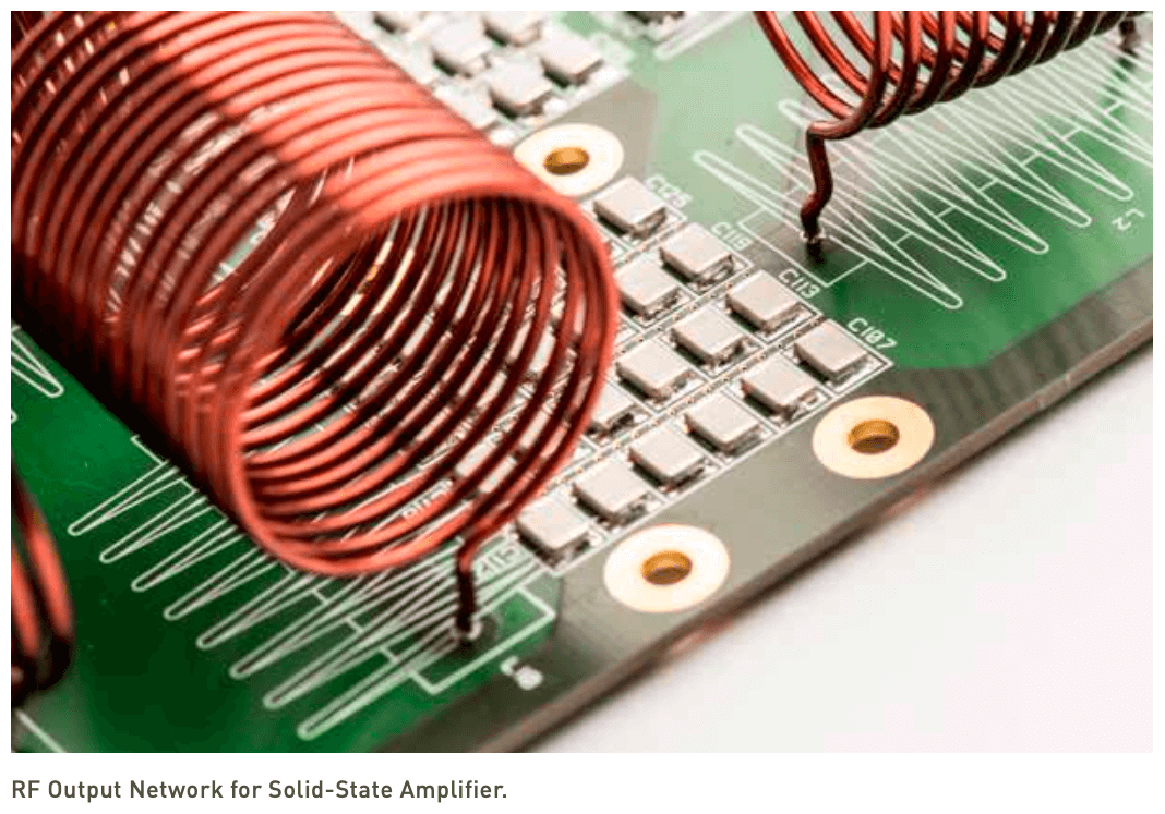 Line Radio Frequency Stages and Solid-State Amplifier (SSA) Modulator
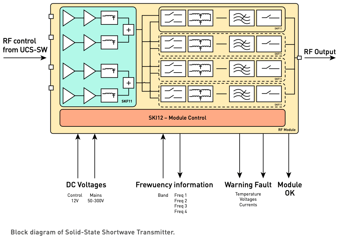 The UCS SW for shortwave applications is the heart of the new control system. It is capable of generating highly accurate RF signals with highest stability and achieving fast direct sampling for RF measurement purposes. The control system comprises the complete audio signal processing path required for shortwave transmission, such as adjustable analog and digital audio inputs, dedicated audio filters, modulation mode and more. The optionally installed embedded DRM modulator completes the entire range of modulation schemes. Analog interfaces, which include fast acquisition channels, allow alarm- and failure-detection within the broadcast transmitter. The UCS system controls the RF power modules. It calculates the phase level of the pushpull amplifier required to provide the output voltage, based upon a reference signal and feed forward regulation. The wide range and fast processing of the reference inputs allows modulation frequencies suitable for analog and digital modulation.
| TECHNICAL SPECIFICATIONS | ||
| Digital DRM | Analog AM | |
| Modulation | DRM standard (ETSI ES 201 980) | DSB: A3E (option A3E with DCC or AMC) |
| Frequency Range (MHz) | 2.3 MHz - 12.1 MHz (standard) 13.57 MHz - 26.1 MHz (optional) |
|
| RF Output Power | peak power: 6.5 kW / 13 kW / 26 kW / 52 kW / 104 kW mean power (with 9 dB crest factor): 0.8 kW / 1.6 kW / 3.2 kW / 6.4 kW / 12.8 kW |
AM carrier power: 1.5 kW / 3 kW / 6 kW / 12 kW / 25 kW |
| Output Impedance | 50 Ω | |
| Permissible VSWR | 2.0 at 50 Ω unbalanced | |
| Mains Power Supply | 400 V, 3-phase and neutral | |
| Frequency | 50 or 60 Hz (±2 Hz) | |
| Power Factor | ≥ 0.9 at nominal AM output power | |
| Overall Efficiency at Pnom | ≥ 70% | ≥ 80% |
| Performance | Out of Band: Compliant ETSI EN 302 245-2 MER: ≥ 30 dB Compliant ETSI EN 302 245-2 (for bandwidth up to 10 kHz) |
AF response: ±1 dB (50 - 10000 Hz) AF distortion: ≤ 2.5% (50 - 10000 Hz) Noise level: ≤ -62 dB rms unweighted |
| Audio Input | DRM/DI | Analog: 0 - 20 dB into 600 Ω balanced Digital: AES3, IEC 60958 and EBU 3250 |
| Local Operation | Local control through push buttons 19" touch-screen optional |
|
| Remote Control & Supervision | Ampegon MasterSeries II software, Web-Interface, SNMP V2c |
|
| Environmental Conditions | Ambient temperature: +1° - +45°C Maximum humidity: 95% non-condensing |
|
| Dimensions | LxWxH: 1.5 / 6 kW 1000 mm x 600 mm x 2150 mm LxWxH: 12 / 25 kW 1000 mm x 1200 mm x 2150 mm |
|
| Personnel Safety | IEC 215, EN 60215 | |
| Specifications may change without notice | ||
| TUBE COMPLEMENT | |||
| RF stages | AF stages and modulator | ||
| Number | Type | Number | Type |
| - | - | - | - |
| THIS TYPE OF TRANSMITTER IS INSTALLED IN THE FOLLOWING COUNTRIES | |||||
| ITU | Country | ITU | Country | ||