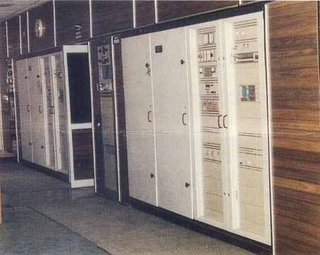
| GENERAL DESCRIPTION |
 * Transistorised RF & AF preliminary stages
| TECHNICAL SPECIFICATIONS | ||
| GENERAL | ||
| Frequency range | 3.2 to 26.1 MHz | |
| Frequency control | Synthesiser | |
| Frequency stability | As per CCIR requirements | |
| Frequency change time | 2 mts. (ave.); 3 mts. (max.) | |
| Type of transmission | A3 broadcasting | |
| Type of modulation | High level plate modulation | |
| Maximum VSWR | 1:1.7 | |
| Cooling system | Condensed vapour cooling | |
| TRANSMITTER | ||
| Carrier power output | 50 kW into 300 Ohm (bal.) | |
| RF harmonics and spurious radiations | According to ITU Radio Regulations, Geneva 1968 | |
| Carrier voltage shift | (Mains voltage drop excluded) <5% from 0 to 100% sinewave modulation at 1 kHz |
|
| Modulation capability | Sinewave modulation (a) Programme material 50Hz to 10kHz with peaks to 100%: Continuous (b) Tone tests (at any frequency between 100 Hz & 5 kHz): 10 mts./hr. at 100% modulation; at 70% modulation 50 mts. continuous (c) Short term test: 100% modulation from 50 Hz to 10 kHz |
|
| Modulation linearity | ±1 dB 100 Hz - 7.5 kHz ±2 dB 50 Hz - 10 kHz |
|
| AF input | 0 dBm into 600 Ohm (bal.) for 100% modulation at 1 kHz | |
| AF response | Within -1 dB & +0.5 dB from 60 Hz to 7.5 kHz at 70% modulation | |
| AF distortion | <4% from 20 to 95% modulation from 100 Hz to 5 kHz <4% upto 80% modulation between 100 Hz & 50 Hz and between 5 & 7.5 kHz |
|
| Hum & Noise level | Better than -55 dB for 100% modulation at 1 kHz | |
| POWER SUPPLY | ||
| Supply voltage | 415 V/380 V, 50 Hz, 3 phase and neutral | |
| Consumption | 150 kVA max. | |
| Power factor | Better than 0.9 at 100% modulation | |
| Overall efficiency at 0% modulation at 30% modulation fm = 1 kHz at 100% modulation fm = 1 kHz Mean value during one day |
Below 15 MHz 64% 58% 58% 60% |
Above 15 MHz 63% 57% 57% 59% |
| ENVIRONMENTAL | ||
| Temperature range | +1°C to +45°C | |
| Relative humidity | 95% max. | |
| MECHANICAL | ||
| Transmitter cabinet | (H) 2100 x (W) 3600 x (D) 1600 mm | |
| Total transmitter installation | (W) 7200 x (D) 6200 mm | |
| Specifications may change without notice | ||
| TUBE COMPLEMENT | |||
| RF stages | AF stages and modulator | ||
| Number | Type | Number | Type |
| 1 | CQK 25-2 | 2 | CQK 25-2 |
| 1 | CQL 2-1 | ||
| THIS TYPE OF TRANSMITTER IS INSTALLED IN THE FOLLOWING COUNTRIES | |||||
| ITU | Country | ITU | Country | ||
| BTN | BHUTAN | IND | INDIA | ||