CCA AM 50,000 D

GENERAL DESCRIPTION


50 kW AM Medium Wave and Short Wave Transmitter AM 50,000 D

photo CCA AM 50,000 D * 
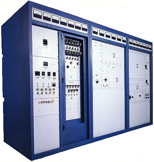
Totally Self-Contained in Three Cabinets Requiring Only 51 Square Feet of Floor Space

* Excellent Audio and Modulation Capability

* Audio Performance Insensitive to Antenna Impedance Changes

* Substantial Reserve Power Output Capability to 10,000 Feet Elevation

* Simple, Basic AM Transmitter

* All Circuits Easily Field Maintainable

* Time Proven Design

* Time Proven Reliability

USES
The CCA AM 50,000 D is a 50KW AM Broadcast Transmitter designed for operation in the Medium Wave and Shortwave bands. Utilizing time-proven simple and reliable circuitry, the AM 50,000 D can be easily installed, operated and maintained under less-than-optimum conditions.

MECHANICAL DESCRIPTION
The CCA AM 50,000 D requires only 51 Square Feet of floor space and is housed in three medium-size cabinets. The AM 50,000 D utilizes reliable vacuum tubes and is state-of-the-art implementation of proven technology.

The AM 50,000 D is air-cooled and access to all components is through rear interlocked and front-hinged doors. Additional access is provided through interlocked panels. Every part and component can be seen by simply opening the appropriate door or panel. Interlocked doors and panels protect personnel from access to all circuitry with exposed terminals operating at 300 volts or greater. Fast-acting bleeder circuitry and automatic shorting of high-voltage power supplies protect personnel from excessive voltages.

Full-size meters display all necessary operating and maintenance parameters. Meters are prominently displayed along the top of all cabinets. Additional status lights indicate operation of control and overload circuitry.

Automatic recycling of the transmitter overload circuits is provided to allow continuous operation if a fault condition is temporary. The overload indicator will remain lit to advise engineering personnel that an overload occurred and to indicate which circuit was at fault. A re-set switch is provided to restore normal status of all indicators.

The AM 50,000 D is cooled by high-volume, high-pressure blowers. Separate blowers for each modulator and the power amplifier are provided within their respective cabinets. Cabinet exhaust fans are also provided with filtered air-intake. All cooling greatly exceeds tube manufacturer recommendations assuring long tube life and reliability.

All transmitter components are self-contained within the three cabinets.

ELECTRICAL DESCRIPTION
RF circuitry begins with a stable crystal oscillator providing two independent switchable circuits. The oscillator output is buffered and amplified to drive the 4-1000A (for Medium Wave) or 5CXI500B (for Short wave) Intermediate Power Amplifier (IPA). A single 4CX35000C tetrode Power Amplifier (PA) conservatively produces 55KW of carrier power at 125% modulation.

The AM 50,000 D audio circuity begins with a solid-state driver amplified by 4CX15000A modulators in the classic push-pull configuration. The modulator output is coupled to the power amplifier through a conventional modulation transformer and reactor configuration. High-level plate-modulation provides superior audio quality, reliability and ease-of-maintenance.

Transmitter control is provided by front panel switches. Reliable and easily maintainable relay logic control is utilized throughout the AM 50,000 D. This circuitry is easily interfaced with most modern remote control systems and metering samples are provided as well. No modification of the transmitter is necessary for remote control interfacing.

All power supplies are solid-state providing reliable, stable and efficient operation. A maximum plate voltage of 10KV is required to achieve rated power output. All power supply components were chosen for long-life and their ability to reliably provide high voltage and currents necessary for operation.

The CCA AM 50,000 D tubes are operated so conservatively that it is realistic to anticipate over 35,000 hours of tube life!

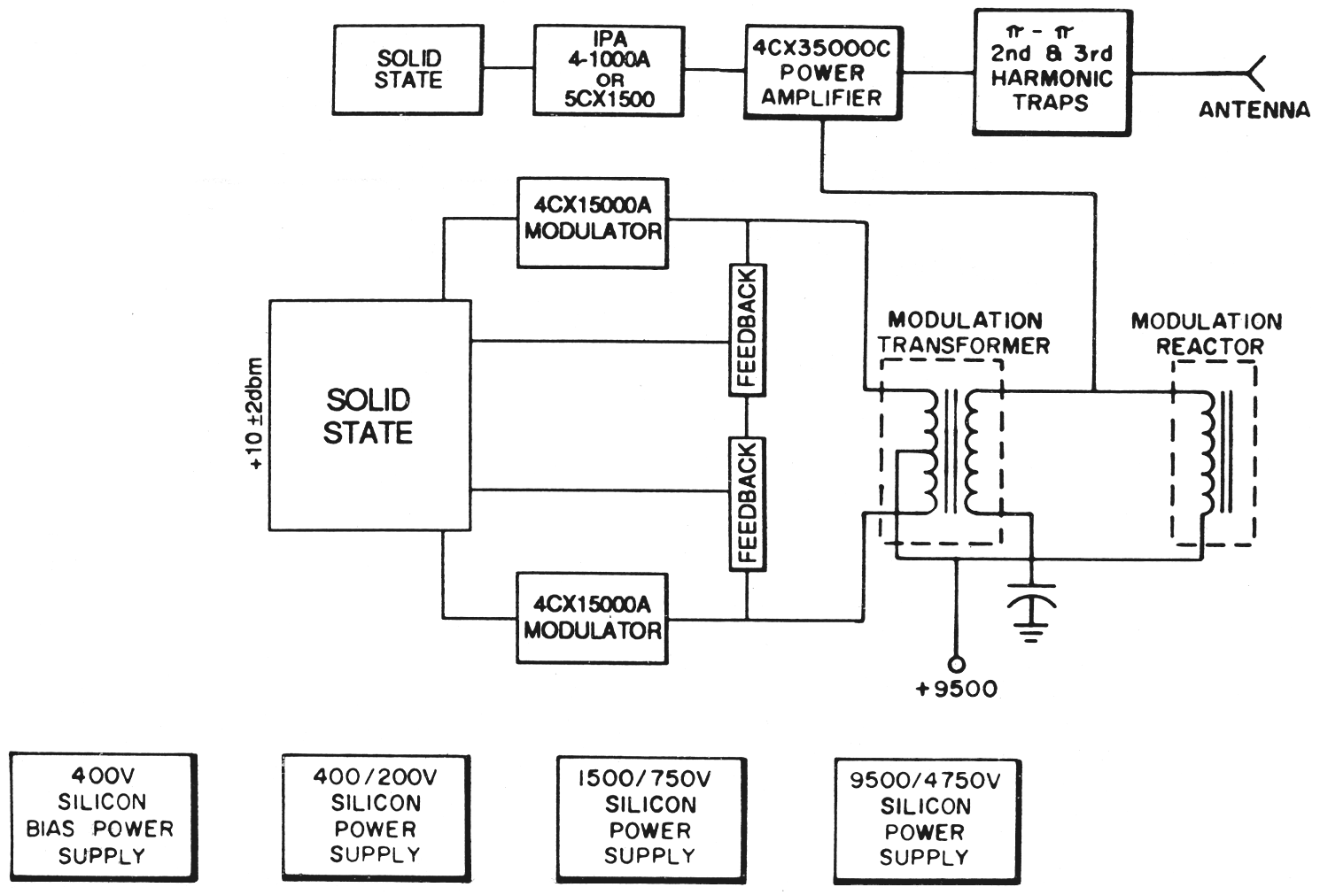
TECHNICAL SPECIFICATIONS
Frequency Range 3 to 17 MHz or 500 to 1600 kHz
Frequency stability ±5 Hz
AF Input Impedance 150/600 ohms
AF Input Level +10 dbm ±2 dbm (for 100% Modulation)
AF Response 50-10,000 Hz @ 95% Modulation ±1.5 db
AF Distortion (90% Modulation) 3%, 50-7500 Hz
Noise Unweighted (below 100% Modulation) 55 db
Modulation High Level
Type of Emission A3
Type of Output (3-1/8" EIA) Unbalanced
Output Impedance (unbalanced) 50-300 ohms
Carrier Shift, 100% Modulation 3% or less
RF Voltage (frequency monitor) 10V, RMS, 75 ohms
RF Voltage (modulation monitor) 10V, RMS, 75 ohms
Power Output Capability 55 kW
Power Supply (Specify)
Line Voltage
Line Frequency

380/460V, 3 Phase
50/60 Hz
Power Consumption
0% Modulation
Average Program
100% Modulation

95 kW
103 kW
140 kW
Power Factor 0.9
Voltage Variation and Regulation ±5%
Spurious Emission (2nd Harmonic & above) 80 db
Operating Ambient Temperature Range 0°C to 50°C
Operating Relative Humidity 100% Maximum
Operating Altitude (specify for higher) 8500 Ft. Max.
Storage Temperature -35° to 60°C
MECHANICAL SPECIFICATIONS
Single Cabinet Size (approx.)
(transmitter requires three cabinets)
48" x 50" x 86"

Floor Space Required 51 Sq. Ft.
Overall Weight (approx.) 9,500 lbs.
Shipping Weight (approx.) 10,000 lbs.
Shipping Cubeage-Ft.3 (approx.)
Per Cabinet (approx.)
485
162
Specifications may change without notice

TUBE COMPLEMENT
RF stages AF stages and modulator
Number Type Number Type
1 4CX35,000C 2 4CX15,000A
1 5CX1500B


THIS TYPE OF TRANSMITTER IS INSTALLED IN THE FOLLOWING COUNTRIES

ITU Country
ITU Country
flag USA USA USA