COLLINS 204F-1

GENERAL DESCRIPTION


photo Collins 204F-1 
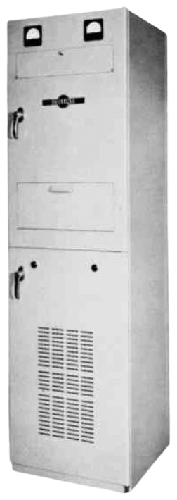
LINEAR POWER AMPLIFIER 204F-1

PHYSICAL DESCRIPTION

All components of Linear Power Amplifier 204F-1 are enclosed in an aluminum cabinet that is painted with a light -grey enamel. This cabinet is self supporting, and is 20 inches wide, 20 inches deep, and 70 inches high. With all components installed, the unit weighs approximately 600 pounds. Upper and lower cabinet doors form the front surface of the cabinet and provide access to all interior areas of the cabinet. Cooling air is drawn into the equipment by an internal blower unit through a filter located on the lower door. Heated air is exhausted through an opening in the top of the cabinet. All power and signal connections are made through the top of the cabinet.

The upper cabinet door provides a mounting surface for two meters and access to the upper half of the cabinet interior. Two hinged access panels in the upper door provide access to all operating controls. The upper half of the cabinet is divided into three compartments. The uppermost compartment is referred to as the input-output compartment. All power and signal functions enter and leave the cabinet through this compartment. The next compartment down from the top of the cabinet 1s referred to as the r-f compartment. This compartment encloses the power amplifier tubes and all the components associated with the anode circuits of these tubes. A small panel located along the upper edge of the compartment provides a mounting surface for the tuning controls associated with the r-f output circuits. These controls are accessible through the upper hinged panel in the upper cabinet door.

The lowest of the three compartments that comprise the upper half of the cabinet is referred to as the grid compartment. All of the components associated with the input and driver amplifier stages, and those associated with the filament, cathode, control grid and screen grid elements of the power amplifier tubes, are located in this compartment. The majority of the components are mounted in a rectangular enclosure that has been named grid box. This enclosure, which ls removable for servicing, is divided into two parts. The input amplifier and both driver amplifier tubes are mounted on the partition that divides the enclosure. All components in the anode circuit of the driver amplifier stage and the filament, cathode, control grid, and screen grld circuits of the power amplifier stage are in the area to the right of this divider wall. (Filament transformer T4 is mounted on the cabinet wall and is not removed from the cabinet with the grid box). The components of the input amplifier stage and the filament, cathode, control grid, and screen grid circuits of the driver amplifier stage are located to the left of the divider wall. The tuning controls associated with the input amplifier and driver amplifier stages are mounted on the front surface of the grid box, and are accessible through the opening normally covered by the lower hinged panel in the upper cabinet door.

The lower cabinet door provides access to the power supply compartment which occupies the lower half of the cabinet. All components associated with the transformation of primary power to the voltages necessary to operate the circuits of the linear power amplifier are located in this compartment. Operating controls for the power supply circuits are mounted on a small panel at the top of the power supply compartment. This panel is hidden from view when the grid box is in place, but the operating controls are brought out through openings in the front surface of the grid box.

TECHNICAL SPECIFICATIONS
Frequency Range 2 to 30 megacycles.
Tuning Manual adjustment to frequency by front panel controls, tap changes, and capacitor changes.
Type of Emission Any type not exceeding bandwidth or power capabilities. Superior for SSB operation.
Bandwidth At least 16 kilocycles wide at 1-db points.
Power Output 2.5 kilowatts peak envelope power or 2.5 kilowatts average power continuously.
Input Impedance 50 ohms.
Output Impedance 50 ohms.
Excitation Required 0.1 watt nominal, 0.2 watt maximum, from external exciter.
SSB Distortion At least 35 db signal-to-distortion ratio.
Power Source 200 to 250 volts, single phase, 50 to 60 cps, six kva capacity.
Specifications may change without notice

TUBE COMPLEMENT
RF stages AF stages and modulator Rectifiers
Number Type Number Type Number Type
2 4CX1000A

2 4B32 or 872A
2 6146

1 5726
1 6CL6


THIS TYPE OF TRANSMITTER IS INSTALLED IN THE FOLLOWING COUNTRIES

ITU Country
ITU Country