COLLINS 205J-1

GENERAL DESCRIPTION


photo Collins 205J-1 205J-1 45 KW HF POWER AMPLIFIER
OA-1448/GRT


Features Applications The 205J-1 is an automatically tuned linear power amplifier with 45 kw PEP output over the 2-30 mc frequency range. A power reduction circuit allows the level to be quickly reduced to 12 kw.
Low distortion amplifiers permit transmission of multiplex signals without mutual interference between subchannels.
The 205J-1, with an external HF exciter and antenna system, provides a complete transmitter for fixed station use. The input level required is only 0.2 watt at the operating frequency. It is especially suited for long range point-to-point or ground-to-air single sideband communication applications. It can be arranged for local or remote control in either attended or unattended operation.
Dependability, long life and savings in size and weight are achieved by modern tubes and components, together with proven single sideband circuitry. The 205J-1 is easily serviced and maintained. All important circuits are metered. Components and wiring are accessible through full length electrically interlocked cabinet doors.

AUTOMATICALLY TUNED

RF and prepositioning information for the tuned circuits of the power amplifier is supplied by an external exciter. Prepositioning information can also be obtained from an internal control panel. Phase discriminator servo systems within the equipment automatically complete the tuning and loading of the three amplifier stages. A pi-L network is used for output coupling. A directional coupler measures the forward and reflected power in the output transmission line.

LOW DISTORTION

Reduced distortion and improved linearity are achieved by the use of approximately 10 db of negative over-all RF feedback in the power amplifier.

AUTOMATIC GAIN CONTROL

Transmitter gain control circuitry permits adjustment of the signal level to operate the power amplifier near its maximum power capability without the possibility of it being overdriven on peaks. Rectified voltage derived from the signal peaks is used to control circuitry in the associated exciter, reducing the excitation level on signal peaks.

AUTOMATIC PLATE DISSIPATION CONTROL

Automatic plate dissipation control circuits allow the power amplifier to operate at full input during the tuning cycle and remove the requirements of high/low power switching with its accompanying problems.

photo Collins 205J-1 CONSERVATIVELY RATED SUPPLIES

Eficient three-phase, full-wave rectifier circuits are used in both plate and screen supplies. The screens of the tubes in the output stage are connected directly to ground to give maximum effectiveness to the screen grid shielding. The PA cathodes are operated 700 v below ground, making the total final amplifier plate supply voltage 7,500 v.
The negative side of the PA plate supply is grounded through the primary of a thyratron trigger transformer. In the event of a high voltage arc to ground, the initial surge of current in the negative return fires a thyratron. This action effectively shorts the high voltage supply to ground.
The low voltage plate and screen supply also use a three-phase, full-wave rectifier. Mercury vapor rectifier tubes are temperature-controlled allowing operation of the power amplifier at low ambient temperatures.

Design Highlights
  1. Separate shielded compartments for each RF stage.
  2. Simplified operating controls are located on recessed panels.
  3. Conservatively rated power supplies have excellent dynamic regulation.
  4. Ceramic tetrode tubes provide high gain with few amplifier stages.
  5. All components and wiring are accessible through full length doors.


Collins 205J-1 diagramCollins 205J-1 diagram

TECHNICAL SPECIFICATIONS
Frequency Range 2-30 mc, automatically tuned.
Output Impedance 50 ohms, 2:1 maximum VSWR. Flange connection for standard EIA 3⅛" 50 ohm transmission line.
Input Impedance 50 ohms unbalanced, termination for type UG-89B/U connector.
Power Output 45 kw PEP; may be reduced to 12 kw PEP. Average output capability is 22.5 kw.
Emission Any type not exceeding bandwidth or power capability. Superior for SSB service.
Input Information Required 
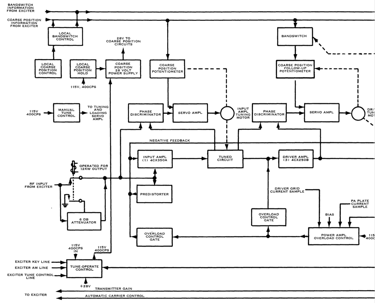
0.2 watt nominal at operating frequency, together with bandswitch and coarse positioning information for automatic operation. Semi-automatic operation only requires RF drive signal.
RF Bandwidth Not less than 16 kc bandwidth between -1 db points.
Distortion Third and higher odd-order distortion at least 35 db below either of two equal tones required to drive the power amplifier to 45 kw PEP.
Harmonic Output Second harmonic at least 50 db down. Higher harmonics at least 60 db down.
Noise level At least 50 db below either of two equal tones required to drive the power amplifier to 45 kw PEP output.
Cooling Required Approximately 2000 cfm of air at a pressure of 0.4" water column, supplied by internally located centrifugal fan.
Primary Power 195-255 v or 350-410 v, 3 phase, either 50 or 60 cps units can be supplied, 67 kva nominal, 0.95 pf for 45 kw PEP output, 2-tone test signal.
Ambient Temperature -29° C to +52° C.
Duty Cycle Continuous.
Specifications may change without notice

TUBE COMPLEMENT
RF stages AF stages and modulator
Number Type Number Type
4 4CX5000A

3 4CX250B

1 4CX350A


THIS TYPE OF TRANSMITTER IS INSTALLED IN THE FOLLOWING COUNTRIES

ITU Country
ITU Country