| GENERAL DESCRIPTION |
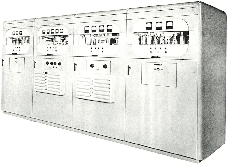 APPLICATION
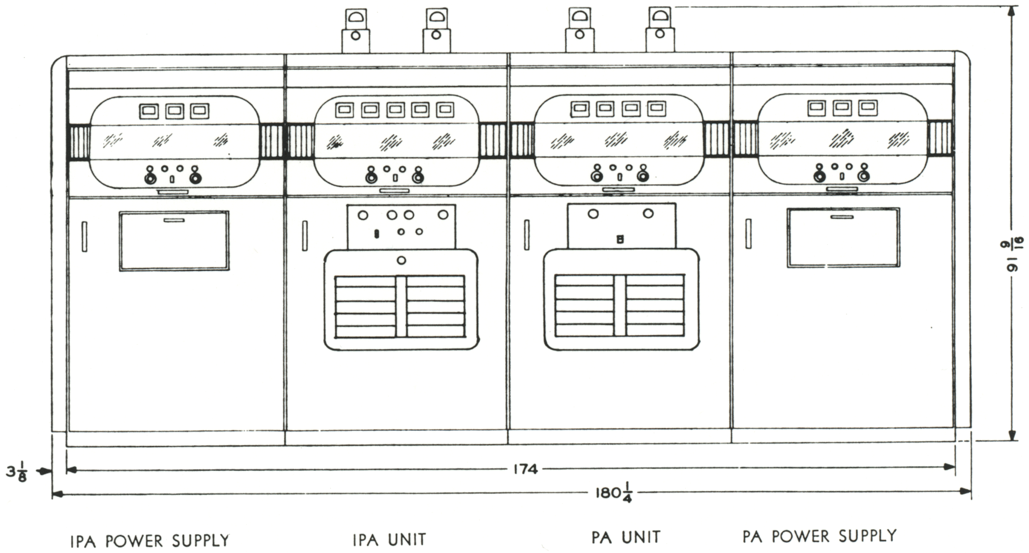
| TECHNICAL SPECIFICATIONS | |
| Dimensions Transmitter IPA plate transformer PA plate transformer |
91 9/16" H, 180 ¼" W, 59 7/16" D 60" H, 57" W, 30 ½" D 32" H, 42" W, 16" D |
| Weight (including transformers) | 12,595 lbs |
| Frequency range | 4.0 to 26.5 mc |
| Crystal type | AN/CR-27/U, fundamental frequency between 2.0 and 4.2 mc |
| Types of emission | A1 (on-off keying); F-1 (frequency shift keying); F-4 (facsimile frequency modulation); A-3a, A-3b or A-9c (single sideband reduced carrier, or composite transmissions) when used with external driving and modulating equipment |
| Keying speed | Up to 400 wpm CW, or 240 dot-cycles per second FSK |
| Number of preset channels | 10 |
| Ambient humidity | Up to 95% |
| Ambient temperature | 32°F to 122°F |
| Power source requirements | 230 volts ±10%, 50/60 cps, 3 phase, and 115 volts ±10%, 50/60 cps, 1 phase |
| Input power | Filaments on, 11.2 kw; high voltage on with key up, 15.6 kw; key down with full power output, 84.5 kw |
| Power Factor | 95% at normal operation |
| Carrier output | CW or FSK, 40 kw; SSB, 30 kw peak envelope power |
| Output impedance | A-1, F-1 or F-4 emission, 600 ohms, balanced with maximum SWR of 2:1; A-3a, A-3b or A-9c emission, 600 ohms balanced with maximum SWR of 1.5:1 |
| TUBE COMPLEMENT | |||||
| RF stages | AF stages and modulator | Rectifiers | |||
| Number | Type | Number | Type | Number | Type |
| 8 | 3X2500A3 | 18 | 4B32 | ||
| 1 | 4-400A | 8 | 3B28 | ||
| 2 | 807 | ||||
| 1 | 6AG7 | ||||
| THIS TYPE OF TRANSMITTER IS INSTALLED IN THE FOLLOWING COUNTRIES | |||||
| ITU | Country | ITU | Country | ||
| LBR | LIBERIA | USA | USA | ||