COLLINS AN/FRT-24

GENERAL DESCRIPTION


photo Collins AN/FRT-24 
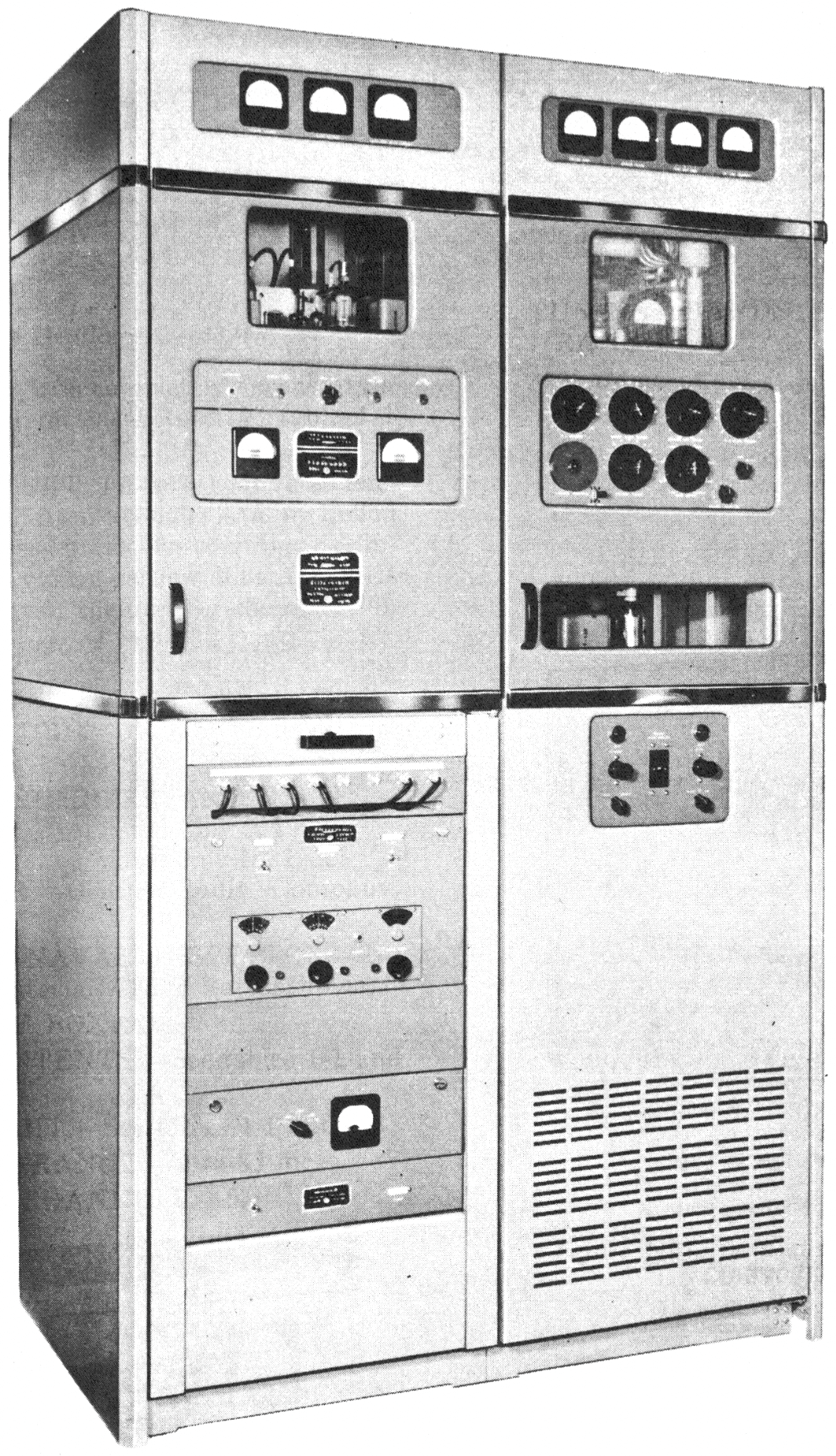
AN/FRT-24 1 KW TRANSMITTER

1. PURPOSE

Radio Transmitting Set AN/FRT-24, is designed for shore-to-ship, ground-to-aircraft, or point-to-point communication application. Radio Transmitting Set AN/FRT-24 provides a maximum output of 1 kilowatt when operating continuous wave radio telegraph (cw) or radiotelephone (mcw) on any frequency within the range of 2 to 30 megacycles. The equipment provides reliable communication for shorestation installations under wide variations in climatic conditions.

2. BASIC PRINCIPLES OF OPERATION

The operation of Radio Transmitting Set AN /FRT-24 is based upon the principle of generating submultiple of the desired output frequency, multiplying the frequency, and amplifying the power of this signal to produce the desired r-f carrier. This carrier is then interrupted or modulated with the intelligence to be transmitted and radiated from a suitable antenna.

A nine-channel crystal-controlled oscillator in the r-f assembly normally supplies the excitation. However, with modifications to the equipment, one to three frequency-shift oscillator assemblies may be incorporated in the r-f assembly to supply this excitation. The excitation signal may also be supplied from R-F Oscillator O-243/FRT-24, through a connector on a patch panel.

The r-f signal passes through a buffer stage, and then through one or two frequency multiplier stages where the crystal frequency is multiplied to produce the carrier frequency. The r-f signal is amplified by the driver amplifier which drives the power amplifier. The power amplifier provides an r-f power output of one-quarter, one-half, or one kilowatt on any frequency between 2 and 30 inc.

Intelligence may be superimposed on the carrier by on-off keying or amplitude modulation. On-off keying is accomplished by interrupting the carrier in the buffer stage. A high-level modulator is used for audio modulation. With modifications to the equipment, frequency-shift keying may be provided by frequency-shift oscillator assemblies (these are not furnished) in conjunction with a keyer circuit in the exciter assembly.

Circuits are provided in the transmitter for protection against equipment damage caused by overloads. The transmitter has interlock switches which remove all dangerous voltages when a cabinet door is opened. During normal operation, all high-voltage circuits are inaccessible from the outside of the transmitter.

Collins AN/FRT-24 diagram
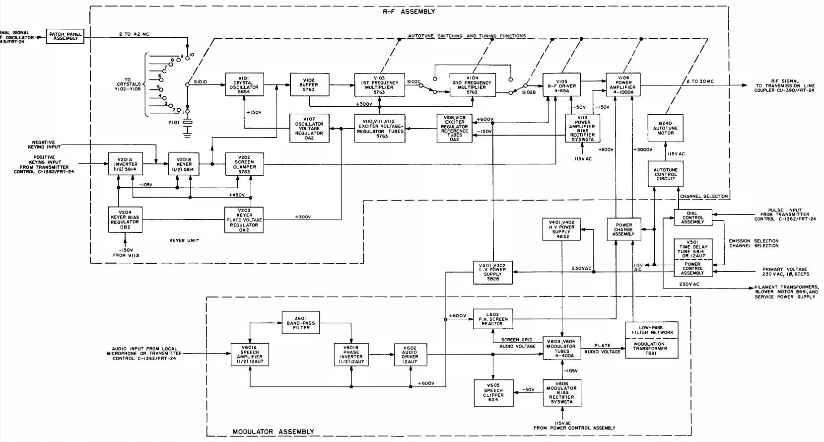
TECHNICAL SPECIFICATIONS
Frequency range 2 to 30 mc
Number of channels 9
Type of frequency control Crystal or stabilized oscillator
Type of emission and modulation capability A-1 (carrier on-off)
A-3 (phone) 100%
Keying speed 600 words per minute (240 dot cycles per second)
Nominal carrier output (1) 250 watts, 500 watts, or 1000 watts for A-1 emission, into a 600-ohm load, with a maximum SWR of 2 to 1
(2) 250 watts, 500 watts, or 1000 watts for A-3 emission, into a 600-ohm load, with a maximum SWR of 2 to 1
Frequency stability (1) With crystal oscillator, .003%
(2) With R-F Oscillator O-243/FRT-24, .004% ±240 cps
Crystals Type CR-18/U
Distortion Less than 5% total harmonic distortion at 1000 cps and 90% modulation when clipping is not used
Noise At least 40 db below 100% modulation
Power source requirements (1) Voltage: 230/208 volts ±10%
(2) Frequency: 50/60 cps ±5%
(3) Number of phases: 1
Ambient temperature range for satisfactory operation 0°C (32°F) to 50°C (122°F)
Maximum relative humidity Up to 95%
Maximum elevation above sea level 10,000 feet
Specifications may change without notice

TUBE COMPLEMENT
RF stages AF stages and modulator Rectifiers
Number Type Number Type Number Type
1 4-1000A 2 4-400A 2 4B32
1 4-65A 2 12AU7 2 3B28
3 5763


1 5654


THIS TYPE OF TRANSMITTER IS INSTALLED IN THE FOLLOWING COUNTRIES

ITU Country
ITU Country
flag USA USA USA