| GENERAL DESCRIPTION |
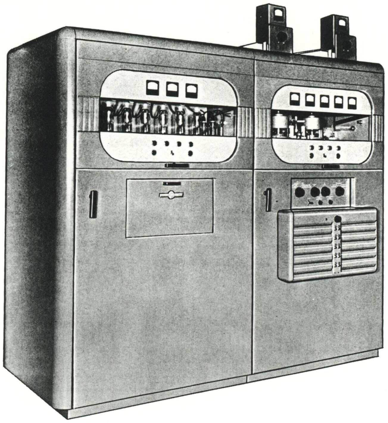 AN/FRT-26 HF RADIO TRANSMITTING SET
| TECHNICAL SPECIFICATIONS | |
| Weight and dimensions Depth Height Width Weight (Total) |
37½" 91-9/16" 93¼" 5,070 lb |
| Frequency range | 4.0 to 26.5 mc |
| Transmitter type | MOPA (Master Oscillator-Power Amplifier) |
| Crystal type | CR-27/U, with fundamental frequency between 2.0 and 4.2 mc |
| Types of emission | A1 (on-off keying); F-1 (frequency-shift keying); F-4 (facsimile frequency modulation); or A-3a, A-3b, or A-9c (single-sideband reduced-carrier, duplex independent-sideband reduced-carrier, or composite transmissions) when used with external driving and modulating equipment |
| Keying speed | 400 wpm cw, or 240 dot-cycles per second FSK, maximum |
| Number of preset frequency channels | 10 |
| Number of tubes | 87 |
| Ambient humidity | 95% maximum |
| Ambient temperature range | 32°F to 122°F |
| Power source requirements Voltage Frequency Number of phases |
230 volts ±10% and 115 volts ±10% 50/60 cps 3 |
| Power output | Normal operation, 15 kw output |
| Power Factor | Normal operation, 15 kw output: 94.5% |
| Nominal carrier output | A-1, F-1 or F-4 emission: 15 kw into 600-ohm load with maximum swr (standing wave ratio) of 2:1 A-3a, A-3b, or A-9c emission: 8 kw peak envelope power |
| TUBE COMPLEMENT | |||||
| RF stages | AF stages and modulator | Rectifiers | |||
| Number | Type | Number | Type | Number | Type |
| 2 | 3X2500A3 | 6 | 4B32 | ||
| 1 | 4-400A | 4 | 3B28 | ||
| 2 | 807 | ||||
| 1 | 6AG7 | ||||
| THIS TYPE OF TRANSMITTER IS INSTALLED IN THE FOLLOWING COUNTRIES | |||||
| ITU | Country | ITU | Country | ||
| PHL | PHILIPPINES | ||||