| GENERAL DESCRIPTION |
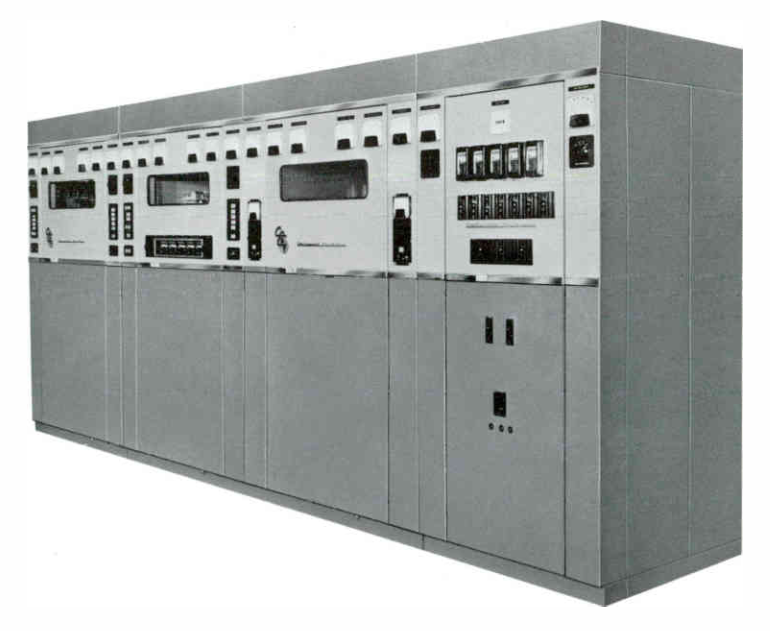 This transmitter is designed for operation in the International short wave broadcast band, and for communication service with frequency shift keying. The Type 417B is manually tuned over the frequency range from 3 to 30 megacycles. Utilizing high-level plate modulation, the Power Amplifier uses a single type ML-6697 air cooled tube which provides high efficiency, increased reliability and ease of servicing as compared to multiple-tube power amplifiers. Light weight, low cost power tubes are operated at 50% or less of their maximum ratings for increased reliability. Solid state rectifiers are used in all power supplies.
| TECHNICAL SPECIFICATIONS | |
| Audio Input Impedance | 150/600 ohms |
| Audio Input Level | +10 ±2 dbm |
| Audio Frequency Response | ±1.5 db, 50-7500 cps |
| Hum and Noise | 55 db below 7500 cycles (95% modulation) |
| Carrier Shift | Less than 3% |
| Type of Modulation | High level plate |
| Frequency Range | 3-30 mc |
| Type of Emission | A3 |
| RF Output Impedance | 150-600 ohms balanced |
| Power Output Capability | 55,000 watts |
| Power Source | 460 volts ±5%, 50-60 cps, 3 phase, 3 wire |
| Power Consumption | 0% modulation 95 kw 30% modulation 110 kw 100% modulation 145 kw |
| Power Factor | 0.9 |
| Specifications may change without notice | |
| TUBE COMPLEMENT | |||
| RF stages | AF stages and modulator | ||
| Number | Type | Number | Type |
| 1 | ML-6697 | 2 | ML-6427 |
| 1 | 4CX5000A | 4 | 304TL |
| 1 | 4-125 | 2 | 4-125A |
| 1 | 6146 | 2 | 6146 |
| THIS TYPE OF TRANSMITTER IS INSTALLED IN THE FOLLOWING COUNTRIES | |||||
| ITU | Country | ITU | Country | ||
| HOL | NETHERLANDS | G | UNITED KINGDOM | ||
| USA | USA | VEN | VENEZUELA | ||