| GENERAL DESCRIPTION |
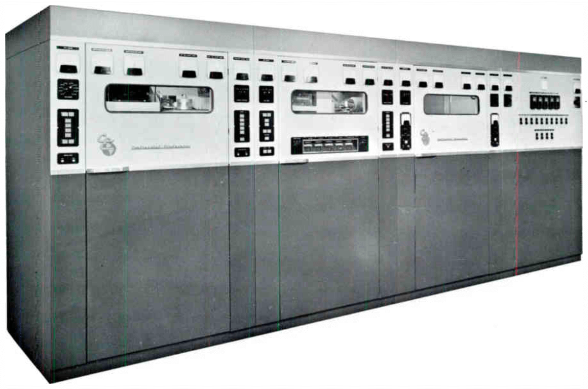 For operation in the International short wave broadcast band, it is high-level plate modulated with trapezoidal modulation capability. Operating over the frequency range from 3.2 to 26.1 megacycles, the 418A uses four amplifier stages to raise input level of 0.5 watts to 100 kw carrier power output. Five front panel controls tune the complete transmitter. A vapor phase system is used to provide efficient, stable cooling to insure maximum tube life. Fast frequency change is accomplished with only four RF stages and the output network to adjust. Tuning is amplified with all RF stages operating at fundamental carrier frequency. Transmitter is fully instrumented, and all operating parameters are displayed on front-mounted, functionally grouped meters. Supervisory controls and equipment protection systems use illuminated push buttons to facilitate control and status monitoring. Solid state rectifiers are used in all power supplies. Individual, externally mounted crystal oscillator/multiplier units preset for each operating frequency may be used in groups, with selective switching to control single or multiple transmitters. Stable, variable frequency oscillators are available. Audio peak clipping amplifiers can be used to increase percentage of modulation by use of trapezoidal wave form.
 Five stages are used to raise audio frequency input from +10 dbm ±2 db, to the modulator output required for 100% modulation. The first is a low gain push-pull stage for compensating for low frequencies as required in trapezoidal modulation. The second and third are conventional push-pull and RC coupled. The fourth is a pair of triodes employed in a push-pull cathode follower circuit and is transformer coupled to modulator grids. A pair of F-8388 triodes are used in a conventional push-pull Class B modulator circuit.
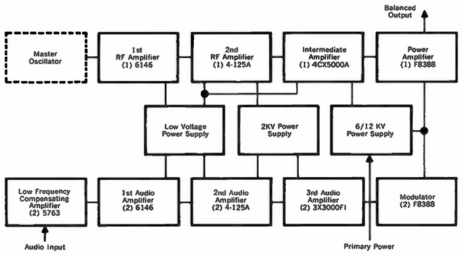
| TECHNICAL SPECIFICATIONS | |
| Audio input impedance | 150/600 ohms |
| Audio input level, 100% mod | +10 dbm ±2 db |
| Audio freq. response | ±5 db, 30-7500 cps |
| Audio distortion | less than 3%, 50-7500 cps, 95% mod |
| Hum and noise | 55 db below 100% mod |
| Carrier shift | less than 3% |
| Modulation | high level plate |
| Freq. range | 3.2 - 26.1 mc |
| Emission | A3 |
| RF output impedance | 300-600 ohms balanced |
| RF input | 0.5 w, 75 ohms |
| Carrier output | 100 kw |
| Power source | 460 v, ±5%, 50-60 cps, 3 phase |
| Power consumption | 0% mod. 196 kw; 30% mod. 215 kw; 90% mod. 275 kw |
| Power factor | 0.9 |
| Specifications may change without notice | |
| TUBE COMPLEMENT | |||
| RF stages | AF stages and modulator | ||
| Number | Type | Number | Type |
| 1 | F-8388 | 2 | F-8388 |
| 1 | 4CX5000A | 2 | 3X3000F1 |
| 1 | 4-125A | 2 | 4-125A |
| 1 | 6146 | 2 | 6146 |
| 2 | 5763 | ||
| THIS TYPE OF TRANSMITTER IS INSTALLED IN THE FOLLOWING COUNTRIES | |||||
| ITU | Country | ITU | Country | ||
| BGD | BANGLADESH | ||||