CONTINENTAL ELECTRONICS 418 F

GENERAL DESCRIPTION


418 F 100 kW Shortwave Transmitter

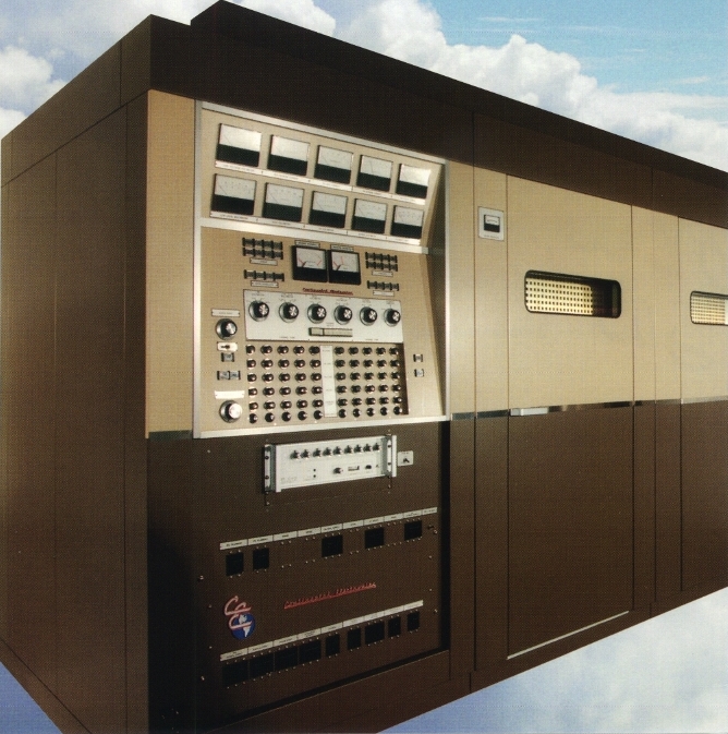
photo Continental Electronics 418 F INTRODUCTION

The Continental Electronics 418 F 100 kW shortwave transmitter is designed for reliable, efficient A3E (AM) operation in frequencies from 3.2 to 22 MHz, or optionally from 2.2 to 16 MHz or 3.95 to 26.1 MHz. In addition to A3E mode, the 418 F is capable of being operated in Controlled Carrier Modulation (CCM) or H3E/R3E Single Sideband (SSB) modes. The 418 F meets or exceeds all CCIR requirements.

All required switchgear, power supplies, protective circuits and cooling equipment are provided as standard equipment, including a harmonic filter, balun and remote control capability. All meters, push button switches and indicators are conveniently arranged in a logical manner on the main front panel. The 418 F includes a unique new PC interface program that allows complete monitoring and control of all transmitter parameters and settings via an IBM-compatible Personal Computer (PC - included)

ADVANCED ELECTRONICS

The 418 F utilizes advanced circuitry and components to provide high quality performance and outstanding reliability. Overall transmitter efficiency is greater than 70% at any depth of modulation. The broadband driver amplifier is a solid-state 200W type. The PA tube is the highly reliable 4CV100,000C and the IPA tube is a 4CX3,000A.

Both of these tubes are available from multiple sources. The 418 F features Continental's patented "Soft-StartTM" circuitry for protection against line variations and surges, thereby increasing tube life.

The 418 F features ten pre-set frequencies utilizing a high-stability frequency synthesizer. The IPA is automatically tuned via a discriminator for optimum IPM performance and reliability in tuning. Typical tuning time for the 10 preset frequencies is 25 seconds over the range of the transmitter frequency range. A highly efficient Pi-L output network is utilized for improved harmonic suppression.

The modulator is totally solid-state, utilizing 46 identical 700 volt power switches configured in series to sequentially and rapidly turn on and off to provide high voltage DC and the superimposed high level audio voltage. Switching is accomplished using advanced Insulated Gate Bipolar Transistors (IGBT). The series connected modules are controlled via fiber optic links with the modulator control unit for positive control and total elimination of any RF interference. Patented (U.S. Patent Nos. 4,896,372; 5,099,203; 5,200,707) circuitry utilizes discrete logic to ensure that each module contributes equally to the overall output power, and in the event of a module failure, effectively removes it from compromising the overall output voltage.

Audio performance is superb, and the modulator efficiency is in excess of 97%. The IGBT's are rated well beyond that which is necessary for peak current demands.

VERSATILE MODULATION MODES

The 418 F may be operated in a variety of modulation modes. Controlled Carrier Modulation (CCM) is a standard feature of the 418 F and provides 100% modulation while allowing RF carrier level to be reduced in preset increments from -1 dB to a maximum of -6 dB during program pauses. Significant savings in operating power consumption can be realized using this mode without adversely effecting audio quality. CCM mode is easily selectable via a front panel switch.

The 418 F may also be operated in H3E or R3E single sideband (SSB) modes when the 418 F is ordered with a modified frequency synthesizer and the SSB modular plug-in circuit boards. SSB mode is accomplished using the phase amplitude method (also called envelope elimination and restoration). Additional modes include ISB, DSB, FSK, and AM Stereo, and may be accommodated on special order.

PROTECTION & SAFETY FEATURES

The 418 F features a wide variety of operational safety and circuit protection advances. High speed VSWR and high voltage overload detectors remove power in less than 50 microseconds. Additional power protection is provided for phase rotation, under-voltage/over-voltage, and conventional overload situations on low-level stages. The solid-state modulator and the PA screen power supplies utilize the same power switch module, each of which has its own overload protection.

All high-power components of the RF amplifier are water cooled. This is a closed system utilizing water only and a water to air heat exchanger. A sealed 17 GPM pump and water purifier provide excellent (2-3 years) water life. If extended freezing conditions are expected to be encountered, a secondary water/glycol cooling system can be supplied as an optional item. Air cooling within the RF amplifier is provided with an internal, shock-mounted blower.

Doors on the power amplifier cabinet offer easy and unobstructed service access to all internal components. Door interlocks and grounding switches are keyed for security.

TUNED BALUN

The 418 F is normally supplied with a tuned balun that delivers RF power to 300 ohm balanced output transmission line, matching this impedance to the unbalanced output impedance of the final power amplifier. The tuned balun may be mounted on top of the power amplifier or any other convenient location.

DUMMY LOAD

A dummy load is available as an option. This dummy load is liquid cooled with film resistor elements delivering load impedances of 50 and 75 ohms unbalanced, or 300 ohms balanced with a VSWR of less than 1.2:1 over the frequency range of 2 to 30 MHz.

INSTALLATION

Upon request Continental Electronics Corporation offers complete or partial site design, equipment installation, custom configuration, and testing services. In-factory training is provided for all facility personnel at no charge. The 418 F may be installed in elevations up to 6,000 feet above sea level in the standard configuration. Higher elevations can be accommodated by special order. Special heating and cooling requirements may be discussed with the Continental staff.

TECHNICAL SPECIFICATIONS
ELECTRICAL
RF Carrier Output Power (A3E) 100 kW (400 kW PEP)
Reduced RF Carrier Output Power (A3E) 25 kW - 100 kW
RF Output Power 2-Tone (H3E) 200 kW PEP
RF Output Power Program (R3E) 300 kW PEP
RF Output Impedance 50 or 75 ohms unbalanced; 300 ohms balanced (balun supplied with transmitter)
Standing Wave Ratio 2.0:1 VSWR at full power
Tuning Time An average of 10 typical frequency changes take less than 25 seconds each
Frequency Range 3.2-22 MHz continuous in 1 kHz increments, (2.3-16 MHz or 3.95-26.1 MHz optional ranges)
AF Power Source Customer specified: 360-480 VAC, 50/60 Hz, 3-phase, other voltages available on request
Efficiency Better than 70%
AUDIO
Modes of Emission AM (A3E), SSB (H3E & R3E)
Modulation Method High level plate modulation using high efficiency solid-state modulator
Modulation Capability 70% continuous; 100% sinusoidal modulation at audio frequencies from 50 to 7,500 Hz for up to ten minutes per hour
Controlled Carrier Level Modulation (CCM) The 418 F is capable of operating in CCM mode, a power saving modulation technique that allows scaling of the carrier amplitude to the modulation percentage, automatically reducing carrier as much as 6 dB
Harmonic and Spurious Radiation Meets or exceeds FCC and CCIR requirements.
Audio Response (A3E) ±0.5 dB from 50 Hz to 4,500 Hz, ±1 dB from 4,500 Hz to 7,500 Hz at less than 70% modulation
Audio Response (H3E & R3E) ±0.5 dB from 100 Hz to 4,500 Hz at any level up to the average power capability
Audio Harmonic Distortion (A3E) Less than 2% at 90% modulation from 50 Hz to 4,500 Hz; 3% from 4,500 to 7,500 Hz
Audio Harmonic Distortion (H3E & R3E) Less than 2% at 90% at full average power capability from 100 Hz to 4,500 Hz
Intermodulation Distortion (A3E, H3E & R3E) At least -35 dB relative to either tone of a two-tone test signal
Carrier Reduction (H3E & R3E) -3 dB to -24 dB relative to PEP, adjustable in 3 dB steps
Audio Input Requirements Adjustable from -8 dBm to +10 dBm for 100% modulation
Audio Input Impedance 600 ohms or 10K ohms, balanced
Carrier Level Shift (A3E) Less than or equal to ±3% shift at 100% tone modulation with 1 kHz sinewave exclusive of powerline variations
Carrier Noise -56 dB unweighted referenced to 100% modulation with a 1 kHz tone
MECHANICAL
Weight 12,320 lbs. (5,587 kg) before packing
Size - Transmitter 60" width (1,524 m)
192" lenght (4,877 m)
85" height (2,159 m)
ENVIRONMENT
Ambient Temperature Range +40°F to +111°F indoors (+5°C to +45°C), +14°F to +111°F outdoors (-10°C to +45°C)
Relative Humidity Range 0 to 95% relative humidity, non-condensing
Altitude Up to 6,000 ft (1,829 m) above sea level
Cooling Water, heat exchanger (supplied), and air cooling
Specifications may change without notice

TUBE COMPLEMENT
RF stages AF stages and modulator
Number Type Number Type
1 4CV100,000C

1 4CX3000A


THIS TYPE OF TRANSMITTER IS INSTALLED IN THE FOLLOWING COUNTRIES

ITU Country
ITU Country
flag CHN CHN CHINA flag KOR KOR KOREA SOUTH
flag LTU LTU LITHUANIA flag MLI MLI MALI
flag PHL PHL PHILIPPINES flag USA USA USA