| GENERAL DESCRIPTION |
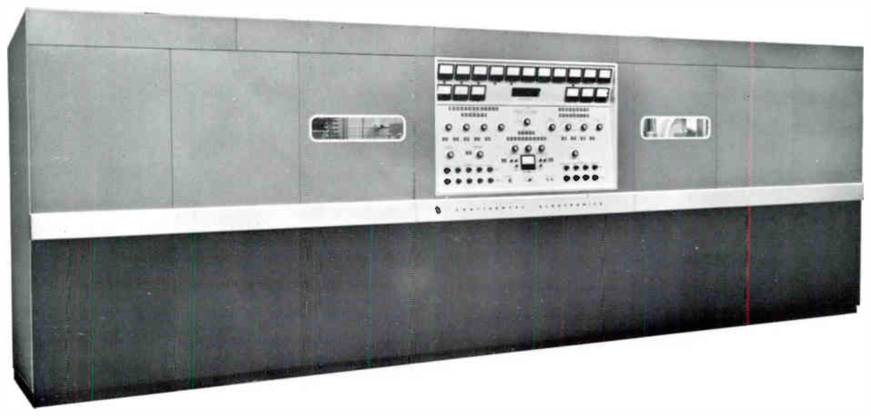 For operation in the International short wave broadcast band, it is a high-level plate modulated transmitter with capabilities for full trapezoidal modulation. The standard 419C continuously covers the frequency range from 3.95 to 26.6 megacycles in four bands. All tuning controls are manually controlled from the front panel. As a customer option, the 419C can be provided with 20 or more pre-set frequencies, enabling the operator to change to any predetermined frequency in less than 20 seconds.
As another option, it can be provided so as to be automatically tuned on any frequency between 3.95 and 26.6 megacycles in less than 40 seconds without operator adjustment. Identical tube types are used for all high-power stages, reducing maintenance and replacement costs. A vapor phase cooling system provides stable operation and relatively small component size. All high-level tuning elements are motor driven ceramic vacuum variable capacitors which are controlled from the central console.
All essential controls, metering positions and status indicators are located on the central console for easy tune-up. All dc power supplies use solid state rectifiers.
For operation in the International short wave broadcast band, it is a high-level plate modulated transmitter with capabilities for full trapezoidal modulation. The standard 419C continuously covers the frequency range from 3.95 to 26.6 megacycles in four bands. All tuning controls are manually controlled from the front panel. As a customer option, the 419C can be provided with 20 or more pre-set frequencies, enabling the operator to change to any predetermined frequency in less than 20 seconds.
As another option, it can be provided so as to be automatically tuned on any frequency between 3.95 and 26.6 megacycles in less than 40 seconds without operator adjustment. Identical tube types are used for all high-power stages, reducing maintenance and replacement costs. A vapor phase cooling system provides stable operation and relatively small component size. All high-level tuning elements are motor driven ceramic vacuum variable capacitors which are controlled from the central console.
All essential controls, metering positions and status indicators are located on the central console for easy tune-up. All dc power supplies use solid state rectifiers. The 419C is completely self-contained. Output from the built-in crystal oscillators and frequency multipliers is fed into a two-stage continuously tuned amplifier. The 125 watt level is amplified to 10 kw by a 4CX-3000A tetrode; then further amplified to 50 kw by an F-8388 vapor cooled tube. The PA develops 250 kw, and an additional 30 kw is fed through the PA to provide a total of 280 kw carrier output. The driver and two PA tubes
are operated in a grounded grid circuit. Tank circuits for the PA are shorted coaxial lines which are bandswitched. Output at 50 ohms impedance level is taken from the coaxial lines and connected to the
Baluns.
The 419C is completely self-contained. Output from the built-in crystal oscillators and frequency multipliers is fed into a two-stage continuously tuned amplifier. The 125 watt level is amplified to 10 kw by a 4CX-3000A tetrode; then further amplified to 50 kw by an F-8388 vapor cooled tube. The PA develops 250 kw, and an additional 30 kw is fed through the PA to provide a total of 280 kw carrier output. The driver and two PA tubes
are operated in a grounded grid circuit. Tank circuits for the PA are shorted coaxial lines which are bandswitched. Output at 50 ohms impedance level is taken from the coaxial lines and connected to the
Baluns.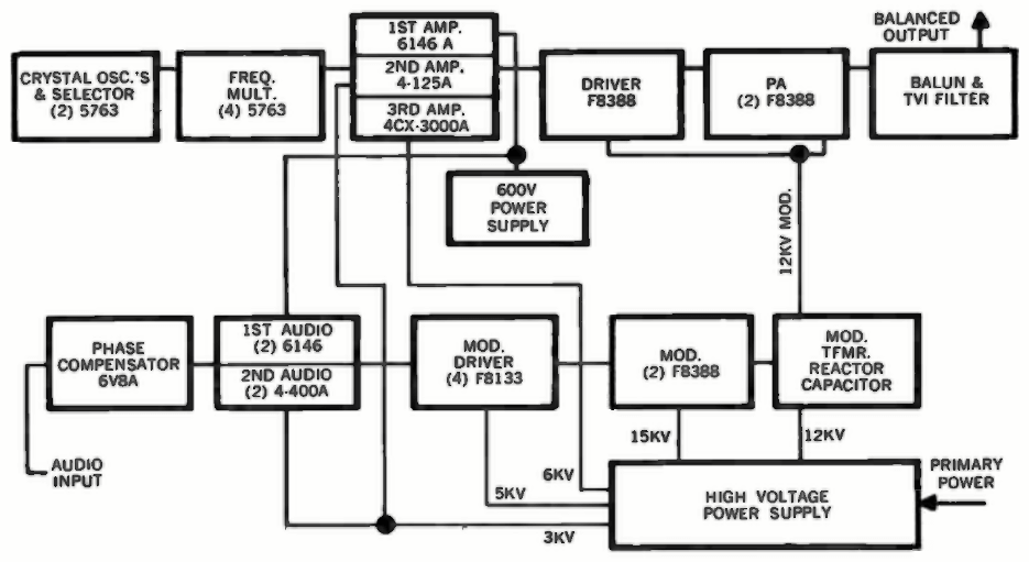
| TECHNICAL SPECIFICATIONS | |
| Audio input impedance | 150/600 ohms |
| Audio input level, 100% mod | +10 dbm ±2 db |
| Audio freq. response | ±1 db, 100-7500 cy; ±2 db 50-10,000 cy up to 95% mod |
| Audio distortion | less than 4% 100-5000 cy; less than 5% 50-100 and 5000-7500 cps |
| Hum and noise | 50 db below 100% mod |
| Carrier shift | less than 5% |
| Modulation | high level plate |
| Freq. range | 3.95 - 26.6 mc |
| Emission | A3 and F1 |
| RF output impedance | 300 ohms balanced |
| Carrier output | 250 kw |
| Power source | 4160 v, ±3%, 50-60 cps, 3 phase |
| Power consumption | unmodulated 455 kw; 100% modulation 680 kw |
| Power factor | 85% or higher |
| Specifications may change without notice | |
| TUBE COMPLEMENT | |||
| RF stages | AF stages and modulator | ||
| Number | Type | Number | Type |
| 3 | F-8388 | 2 | F-8388 |
| 1 | 4CX3000A | 4 | F-8133 |
| 1 | 4-125A | 2 | 4-400A |
| 1 | 6146A | 2 | 6146 |
| 6 | 5763 | ||
| THIS TYPE OF TRANSMITTER IS INSTALLED IN THE FOLLOWING COUNTRIES | |||||
| ITU | Country | ITU | Country | ||
| HOL | NETHERLANDS | ||||