CONTINENTAL ELECTRONICS 420 A

GENERAL DESCRIPTION


photo Continental Electronics 420 A 
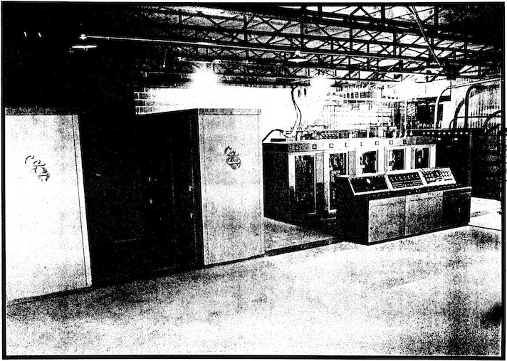
The Type 420A transmitter has been designed for AM operation in the International Shortwave Broadcast Band from 5.9 to 21.75 megacycles with an output power of 500,000 watts carrier, to which modulation of 100% may be applied.

A combination of two Type 420A transmitters, representing a total power of 1,000,000 watts (but without means of combining for single transmission line output) for installation in the same transmitter building, has been designated the Continental Type 106B. When the Type 420A transmitters are bought for this method of installation, the auxiliary 230-volt supply transformers are provided with sufficient capacity so that one transformer bank supplies both 420A transmitters with auxiliary power. The metal-clad 5,000-volt switchgear is also combined in a single switchgear cubicle for the two Type 420A transmitters, this cubicle containing a plate circuit-breaker for each Type 420A transmitter and a circuit-breaker for the primary supply to the afore-mentioned auxiliary transformer bank.

Electrical Design

The Type 420A, 500-kilowatt shortwave transmitter, uses two 250 kilowatt linear high-efficiency output amplifiers, each with its own associated modulated amplifier. The outputs of the two 250 kilowatt amplifiers are combined in a network to feed a single 300-ohm balanced transmission line. The two modulated amplifiers are driven by a common driver unit which supplies radio frequency excitation for their grids, and audio modulation for grid bias modulation of these amplifiers.

All metering and tuning controls for the power amplifiers and modulated amplifiers are centralized on control consoles situated remotely from the amplifiers. Metering and control for the driver unit are located on its front panel, but for normal operation the control of this unit is integrated with the general control system for the entire transmitter and operated from the control console.

The Driver Unit is installed in line with four other units: The Driver Plate Rectifier Unit, H, the Bias Rectifier Unit, G1, for Amplifier No. 1, the Bias Rectifier Unit, G2, for amplifier No. 2, and the 15 Kilovolt Plate Rectifier Unit, F. These five units are housed in Trans-View type cabinets and are all similar in appearance.

The 230 Volt Distribution Panel, the Water Cooling Systems, the Water Monitor Panels, a matching resistor used in conjunction with the Combining Unit, a Line Impedance Matching Unit, and a Power Equipment associated with the rectifier and filter, comprise the balance of the equipment for the Type 420A transmitter.

Fundamental Circuit

Control of the operating carrier frequency is provided in a frequency generator unit, K, located on a relay-rack type cabinet from which a shielded cable is run to the Driver Unit, A. This Frequency Control Unit, K, contains mounting positions for 10 crystals, plus additional positions for one RCA Type G-31 crystal and oven, and one General Electric Type G-31 crystal and oven. There are also external connections for a variable frequency oscillator, a frequency shift keying device, and a phase shift modulator with switching arrangements for connecting these other signal sources.

Radio frequency energy from the frequency generating unit is supplied to the buffer stage of the Driver Unit, A, which uses a Type 807 tube. This buffer stage is followed by two radio frequency amplifiers, the first using one Type 4-125A tetrode and the second using two Type 4-1000A tetrodes. The radio frequency output available from this driver is approximately 5 kilowatts, which is sufficient power for supplying both modulated amplifier grid circuits. The Driver Unit contains a 4-stage audio amplifier, the fourth stage being a cathode follower molulator with four tubes in paralled. This modulator applies grid bias modulation to the bias of the modulated amplifier stage.

The two 250 kilowatt amplifiers are identical. Each consists of a Modulated Amplifier using two ML-5681 tubes in a push-pull Class C grid bias modulated amplifier, which drives the grid circuit of the 250 kilowatt linear amplifier. This linear amplifier uses four Type ML-5682 tubes in a Doherty high efficiency circuit, with two of the tubes in push-pull operating as the carrier, or No. 1 tube, of the Doherty circuit, and two tubes in push-pull operating as the peak, or No. 2 tube, of the Doherty circuit.

In this transmitter the carrier tubes are operated with a grounded grid connection, whereas the peak tubes are operated with the cathodes grounded in the conventional manner.

The output of each 250 kilowatt amplifier feeds into a bridge-type combining network using a balancing resistor to maintain equalization of the load on the two amplifiers so preventing the transfer of power from the terminals of one amplifier to another.

The Combining Network delivers power into an impedance matching network designed to provide proper terminating impedance over the operating range of frequencies, and for transmission lines having standing wave ratios of up to 1.3 to 1.

Overall rectified RF feedback is used for the reduction of noise and distortion.

TECHNICAL SPECIFICATIONS
Carrier Output Power 1/2 megawatt
Type of Emission A3 Telephone (with provision for certain other types)
Frequency Range 5.9 to 22 megacycles
Frequency Stability (Crystal Oscillator) 0.003%
Type of Modulation Grid bias in penultimate stage
Type of Power Amplifier Linear High Efficiency
Output Impedance 300 ohms balanced
Audio Frequency Impedance 150/600 ohms
Audio Frequency Input Level +10 dbm ±2 db
Modulation Capability From 50 to 10,000 cycles: 100%
Power Consumption Unmodulated: 1100 kw
100% Modulation Level: 1600 kw
Power Line Requirements 4160 volts, 60 cycles, 3 phase 3 wire
Instantaneous Regulation of Power Source Not to exceed 5%
Voltage Variation Not to exceed 5%
Audio Frequency Response Uniform within ±1 db from 30 to 10,000 cycles
Residual Carrier Noise 54 db below 100% modulation
Audio Frequency Distortion Less than 5%
Maximum time required for Frequency Change 3 minutes
Specifications may change without notice

TUBE COMPLEMENT
RF stages AF stages and modulator
Number Type Number Type
8 ML-5682 4 ML-5681
2 4-1000A 5 845
1 4-125A 2 807
1 807


THIS TYPE OF TRANSMITTER IS INSTALLED IN THE FOLLOWING COUNTRIES

ITU Country
ITU Country
flag E E SPAIN flag USA USA USA

(Credit for providing info on this transmitter goes to Glenn Swiderski)