CONTINENTAL ELECTRONICS 420 C

GENERAL DESCRIPTION


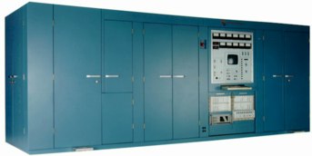
Type 420 C 500 kW Shortwave Broadcast Transmitter

photo Continental Electronics 420 C INTRODUCTION

The Continental Electronics 420 C transmitter is a versatile, state-of-the art, high efficiency 500 kW shortwave transmitter. It is capable of being operated in standard amplitude modulation, controlled carrier level modulation or single sideband service.

From a central master control panel or from a remote computer control and monitoring station, this transmitter may be set up and pretuned or automatically tuned to deliver full carrier power at any frequency between 3.9 and 26.1 MHz. It may be manually tuned using controls and indicators located on the central master control panel.

The Continental Electronics type 420 C transmitter described herein employs some of the most technologically advanced components available today. The highly efficient modulator uses the latest insulated gate bi-polar switching transistors, and the final power amplifier uses the most modern tetrodes. All components and circuitry have been selected to provide optimum performance and reliability.

The type 420 C transmitter power amplifier operates equally well using either the Varian 4CM400,000 or the Thomson CSF TH558 tetrodes.

All critical major components of the RF amplifier such as vacuum tubes and vacuum capacitors are either water or water-vapor cooled. Dual loop liquid cooling systems can be provided when required by freezing conditions. In this case, the secondary or outside cooling system will use a water/ethylene glycol coolant. The highly efficient solid state modulator is air cooled.

The transmitter includes all required switchgear, power supplies, protective circuits, amplifiers, controls, as well as cooling and peripheral equipment. It is compact in design yet easy to service and maintain. Particular care in the design has been given to operational reliability and efficiency, resulting in a transmitter capable of providing high quality broadcast service with minimum maintenance and down time.

EFFICIENT RELIABLE CIRCUITS

The transmitter employs anode modulation of the final RF power amplifier stage to achieve amplitude modulation (A3E) transmissions. The single sideband modes (H3E and R3E) with both full and reduced carrier level, are accomplished with anode modulation of the RF power amplifier stage and phase modulation of the frequency synthesizer. The power amplifier stage operates in the Class C condition which provides the highest RF amplifier efficiency and the same tuning and loading conditions for all of the operational modes.

HIGH "Q"

Key to the RF performance of the transmitter is the power amplifier output network. The 420 C uses a High Q, dual transmission line coupled cavity followed by a T network and VHF filter that provides the desired impedance transformation and attenuates any spurious and harmonic signals to acceptable levels. The dual transmission line coupled cavity is essentially free of any parasitic resonances which ensures a highly stable transmitter over the continuous 3.9 to 26.1 MHz tuning range. Each copper transmission line of the cavity is terminated at its far end by a movable terminating plane. Contact of the plane to the lines and to the walls of the cavity is through a multiplicity of pneumatically activated, silver alloy contacts. Contacts are released automatically during tuning, and the plane is moved only during the "no power" mode. Capacitors are used for fine tuning.

Typical average tuning time for 10 auto-tune frequencies is 25 seconds. The transmitter can be tuned to any frequency between 3.9 and 26.1 MHz in less than 30 seconds.

The high efficiency solid state modulator consists of 48 series-connected 700 volt switch modules which are sequentially and rapidly switched on and off to provide the anode voltage necessary for the carrier level and any desired depth of modulation up to 100%.

An overall modulator efficiency of greater than 95% is assured through the use of the conservatively rated, fast switching insulated gate bi-polar transistors.

The modular configuration of the system provides redundancy and gradual lowering of the transmitter output power level in the event of a switching module failure. Loss of one switching module results in about a two percent reduction in peak transmitter output power, and normal transmitter operation continues uninterrupted. The audio bandwidth is flat within +1 dB from 50 to 7500 Hz and the total harmonic distortion is less than 3%. Squarewave performance with less than 5% tilt or overshoot assures an accurate reproduction of complex audio processing.

The modulator is capable of supplying PA anode voltage at any level required to operate the transmitter up to the full power output level. The power output level of the transmitter is controlled by "Raise" and "Lower" switches that adjust the level in 0.1 dB steps from the transmitter control panel or from a remote location.

CCM & SSB OPERATION

Controlled carrier-level modulation (CCM) and single sideband (SSB) operation are standard features of the transmitter. CCM and SSB are selectable from switches on the transmitter control panel, or via remote control. The CCM system adjusts the level of the RF carrier when the transmitter is in the AM mode, such that the carrier is maintained at a sufficient level so that the peak audio program level will result in 100% modulation. During program pauses, the carrier level will fall to a preset level of from -1 dB to -6 dB of the full carrier level. With CCM operation, the total input power consumption may be reduced as much as 20 to 25 % from the non CCM power requirement.

Single sideband operation is accomplished with the envelope elimination and restoration technique which is also known as the phase-amplitude method. This allows high power SSB operation with the same high efficiency of AM. Carrier level is adjustable from -6 to -24 dB in 3 dB steps. Unwanted products are >35 dB below either tone of a two tone signal of full PEP.

ACCESSIBILITY

Several doors on the power amplifier cabinet give easy, uncluttered access to interior components. The modulator and other sub-systems can be reached in a walk-around mode.

All door interlocks and grounding switches are safeguarded by a keyed door lock system.

REMOTE & LOCAL CONTROL

Local control and monitoring of all transmitter functions is accomplished at the transmitter local control panel. Meters, push button switches and illuminated displays are arranged to provide user friendly operation. A conventional computer keyboard is provided as a part of the panel. The operator can select a multitude of control, status and monitoring functions through simple and easily learned mnemonics.

Remote control and monitoring of the transmitter is through a remote control port at 19,200 bps, 8 character bits and one stop bit. Either RS232 or RS422 is available, although RS422 is recommended.

The command mnemonics can be modified, if desired, to allow a user to employ the same mnemonics as may be used in presently existing equipment. In addition, this remote system can be easily modified to accommodate multiple transmitter installations and to provide other control functions such as control of RF output matrixes, antenna slewing switches, program audio matrixes, etc.

INSTALLATION

Because most transmitter installations are different from one another, there is no single installation plan that can be universally appropriate. Continental Electronics recognizes this and stands ready to assist customers in the installation planning. Installation and commissioning supervision can also be supplied, or the entire installation and commissioning effort can be provided.

The typical installation layout can be modified to suit almost any building configuration. The only constraint is that the two power transformers and the solid state modulator must be in the same relative positions.

Heat exchanger requirements are dependent on expected environmental conditions. The area is the maximum that is likely to be required.

Because the transmitter becomes a significant part of any transmitter building, the 420 C transmitter can be provided painted in almost any two-tone color scheme desired.

OPTIONAL EQUIPMENT

Tuned Balun
An optional tuned balun can be mounted on top of the power amplifier cabinet, or in any other convenient location.

The balun delivers RF power to a 300 ohm balanced output transmission line, matching this impedance to the unbalanced output impedance of the final power amplifier. The highly efficient variable inductor employed is resonated by two parallel, water cooled, variable vacuum capacitors.

Dummy Load
An optional, liquid cooled, compact dummy load using very stable deposited film resistor elements, with load impedances of 50 or 75 ohms unbalanced and 300 ohms balanced, is available.

TECHNICAL SPECIFICATIONS
RF Carrier Power (A3E) 500 kW on all frequencies through the 3.9 to 26.1 MHz range.
Reduced RF Carrier Output Power (A3E) Any power level between 50 kW and 500 kW.
RF Output Power (H3E & R3E) 1000 kW PEP Two-Tone, 1500 kW PEP Program Modulation.
Frequency Range 3.9 to 26.1 MHz continuous in 100 Hz increments.
Tuning Time An average of 10 typical frequency changes take less than 25 seconds each.
Standing Wave Ratio 2.0:1 VSWR at full power.
Output Impedance 75 ohms or 50 ohms unbalanced, 300 ohms balanced.
Modes of Emission AM (A3E), SSB (H3E & R3E).
Modulation Method PA anode modulation using high efficiency solid state modulator.
Modulation Capability 100% sinusoidal modulation at frequencies from 50 to 7,500 Hz, for ten (10) minutes per hour.
Up to 70% modulation on a continuous basis.
Controlled Carrier Level Modulation The Type 420 C Transmitter has the capability of operating in a controlled carrier modulation mode (CCM).
This is an amplitude modulation technique that scales the amplitude of the carrier to the percentage of modulation.
The carrier can be reduced as much as 6 dB below the rated value.
This feature can be a major cost saving to the user.
Single Sideband Operation (H3E & R3E) Single Sideband (SSB) operation is provided using a phase-amplitude method of generating the single sideband signal.
RF Spurious Noise Less than 50 mW. Out of band emissions are in compliance with CCIR 328-5.
RF Harmonic Outputs Less than 50 mW.
Audio Response (A3E) ±1 dB from 50 Hz to 7,500 Hz at 70% modulation or any lower modulation level.
Audio Response ±1 dB 100 Hz to 4,500 Hz at any level up to the average power capability.
Audio Harmonic Distortion (A3E) Less than 3.5% at 90% modulation from 50 to 7,500 Hz.
Audio Harmonic Distortion (H3E & R3E) Less than 3.5% at full average power capability from 100 to 4,500 Hz.
Intermodulation Distortion (H3E & R3E) At least -35 dB relative to either tone of a two-tone test signal.
Carrier Reduction (H3E & R3E) -6 dB to -24 dB relative to two audio tone PEP output, adjustable in 3 dB steps.
Audio Input Requirements Adjustable from -8 dBm to +10 dBm for 100% modulation.
Audio Input Impedance 600 ohms, or 10K ohms, balanced.
Carrier Level Shift (A3E) Less than or equal to ± 3% shift at 100% ton modulation with 1,000 Hz sinewave exclusive of power line variations.
Carrier Noise -56 dB unweighted referenced to 100% modulation with a 1,000 Hz tone.
Power Source 4,160 Vac, or 11,000 Vac, 3 phase, three wire, 50/60 Hz.
Other voltages may be accomodated on special order.
Main power requirement is 1,200 kW with a 100% tone modulation condition and equal to or greater than 0.95 lagging power factor.
Efficiency The overall efficiency of the Type 420 C Transmitter measured as an average of ten frequencies
over the range 3.9-26.1 MHz at 500 kW carrier power level will not be less than 73% with any depth of modulation.
Overall efficiency of 75% is expected during cool weather conditions and at the lower RF frequencies.
Ambient Temperature +5 to +45° Centigrade, indoors -10 to +45° Centigrade, outdoors.
Lower temperatures may be accommodated on special order.
Altitude Up to 2,000 meters above sea level. Higher altitudes may be accommodated on special order.
Relative Humidity 0 to 95%, non-condensing relative humidity.
Cooling Water, water-vapor, and air cooling is employed.
All necessary cooling is an integral part of the Type 420 C Transmitter.
Demineralized water requirements are less than or equal to 1 gallon per day.
No discrete air ducting is required.
Specifications may change without notice

TUBE COMPLEMENT
RF stages AF stages and modulator
Number Type Number Type
1 4CM400,000A/AG or 4CM500,000G
or TH558 or TH576 or RS 2078 or BEL550,000CX


1 3CW20,000A7


THIS TYPE OF TRANSMITTER IS INSTALLED IN THE FOLLOWING COUNTRIES

ITU Country
ITU Country
flag CHN CHN CHINA flag QAT QAT QATAR
flag USA USA USA