| GENERAL DESCRIPTION |
 In this new 250,000 watt high frequency broadcast transmitter, complete tuning to any one of twenty channels or, with optional synthesizer, to any frequency between 3.95 Mc. and 26.5 Mc. can be made in 20 seconds or less from either a local control or a remote console located up to two miles from the transmitter. The automatic tuning feature eliminates most of the down time for frequency change which can now be performed in the same amount of time normally used for station breaks. This time saving provides as much as one hour per day of additional on air programming for short wave broadcasters. The result is much more efficient operation due to maximum utilization of frequency and program schedule.
| TECHNICAL SPECIFICATIONS | |
| Power Output | 250,000 Watts |
| Frequency Range | 3.95 Mc. - 26.50 Mc |
| Frequency Stability | ±5 ppm |
| Tuning Time | 20 sec. max. |
| Carrier Shift | 5% max. |
| Output Impedance | 300 ohm balanced |
| VSWR | 1.5 to 1.0 |
| Modulation Capability | 100% trapezoidal |
| Modulation Duty Factor | Continuous |
| Audio Input Level | +10 dbm |
| Audio Input Impedance | 600/150 ohms |
| Audio Response | 50-10,000 cps., ±2 db |
| Audio Distortion | 5% maximum |
| Noise Level | -50 db. unweighted |
| Harmonic & Spurious Radiation | -80 db. or better |
| Power Input Voltage | 4160 V ±3%, 3 phase, 3 wire, 50 or 60 cycles as ordered |
| Power Factor | .94 |
| Power Consumption | 0% modulation 400 KW. approx. 30% modulation 500 KW. approx. 100% modulation 590 KW. approx. |
| Over-All Efficiency | Approximately 55% at 100% modulation |
| Altitude | Sea level to 6,000 feet. |
| Temperature | 0°C to +50°C |
| Humidity | 0-95% max |
| Packed Weight | 52,000 lbs. |
| Cubage | 2899 |
| Size | Power amplifier 20' L. x 8' H. x 7' D. Modulator 6' L. x 7' H. x 6' D. Power Supply 16' L. x 25' W. x 12' H. |
| Size of Largest Unit | 20' L. x 8' H. x 7' D. |
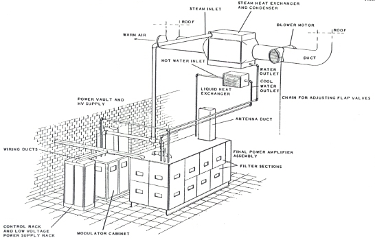
| Cooling | Vapor phase cooling for power amplifier and modulator. Closed circuit water for PA inductor. Other units forced air cooled |
| Specifications may change without notice | |
| TUBE COMPLEMENT | |||
| RF stages | AF stages and modulator | ||
| Number | Type | Number | Type |
| 2 | 4CV100,000C | 2 | 4CV100,000C |
| 1 | 4CX15,000A | 2 | 8122 |
| 2 | 8122 | 2 | 6CG7 |
| 1 | 8072 | - | - |
| 5 | 8203 | - | - |
| THIS TYPE OF TRANSMITTER IS INSTALLED IN THE FOLLOWING COUNTRIES | |||||
| ITU | Country | ITU | Country | ||
| PHL | PHILIPPINES | ||||