GATES HF-100

GENERAL DESCRIPTION


100,000 WATT HIGH FREQUENCY BROADCAST TRANSMITTER

Model HF-100


photo Gates HF-100 
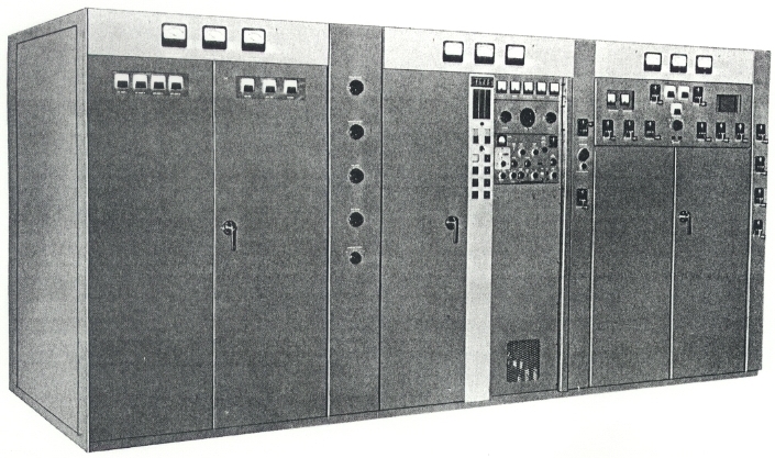
Continuous tuning from the front panel over the entire High Frequency band of 3 Mc. to 26.1 Mc. is only one of the many outstanding and exclusive features of the Gates HF-100 transmitter. Delivering 100 KW power output, the transmitter employs reliable high level modulation for high fidelity broadcasting in the international short wave bands. Air cooled and designed with conservatively rated components, unsurpassed reliability is provided even when operated in areas of extreme temperature and humidity and in 24-hour a day service. Silicon rectifiers that operate well below maximum ratings are included in all power supplies. Added reliability is obtained by the use of oil-filled modulation and power components and the use of variable vacuum capacitors in all major amplifier circuits.

The HF-100 transmitter is also available for telegraph service and can be supplied without the modulator for 100KW CW operation, with high speed keying and frequency shift keying easily accommodated.

CONTINUOUS TUNING: A new, field-proven concept of plate tank circuit design permits continuous tuning over the entire frequency range from the front panel.

This advanced design incorporates only one tuned line tank circuit to allow continuous coverage of the wide frequency range (3 to 26.1 Mc.). As this circuit is permanently mounted within the transmitter, complete coverage is obtained without the inconvenience of plug-in or manually changed power amplifier or output coils. Time-consuming internal component changes and storage problems are eliminated in the Gates 100 KW transmitter. With continuous front panel tuning, the transmitter can be adjusted from one pre-logged operating frequency to another within three minutes or less. This unique Gates design achievement contributes significantly to maximize on-air time for short wave broadcasters.

COMPACT SIZE: The electrical design of the Gates HF-100 transmitter utilizes new, efficient, high-power, air- cooled tubes and tuned lines that permitted a simplicity of mechanical construction resulting in a compact size. Three main transmitter cubicles are mounted in line . . . modulator, control and power amplifier sections. Other equipment consisting of the blower, high voltage and magnetic components are floor-mounted externally.

All three main HF-100 transmitter cubicles are easily accessible from both front and rear. Vertical and walk-in construction design permits easy servicing and fast accessibility to components and tubes. Removable sides provide quick access to the power amplifier tank and output sections, if necessary. Service lights and outlets are provided for convenience in servicing and maintenance.

DUAL SILICON HIGH VOLTAGE POWER SUPPLIES: For greater reliability and better regulation, two separate HV supplies are used in the HF-100 transmitter. One HV supply provides 15KV for the modulator and the other HV supply provides 12.5KV for the power amplifier.

Both HV supplies utilize conservatively rated silicon rectifiers for long trouble-free service over a wide range of temperature, humidity and altitude conditions.

As an example, the high voltage silicon bridge rectifier diodes are capable of a direct current output of 75 amperes, as related to an average demand of approximately 10 amperes.

Full transient protection is provided for silicon cells in every power supply. Each is shunted with a transient suppressing capacitor and resistor.

QUIET OPERATION: The use of a highly efficient forced air cooling system provides a quietness of operation almost unbelievable for a 100,000 watt transmitter. Air flow is controlled to insure maximum cooling with a minimum of air noise. The rugged construction aids in the achievement of the ultimate in low noise operation.

RADIO FREQUENCY CIRCUITS: The exciter is an independent self-powered unit of pull-out construction built into the control cubicle. It has provision for selecting from any one of ten crystal positions and also provides an input for an external VFO and for FSK operation.

Only three amplifier stages are employed to raise the output of the RF exciter to the rated 100 KW transmitter power output. The intermediate power amplifier utilizes one type 4-65 tube followed by two type 6076 RF drivers. Continuously adjustable, the RF driver is conservatively rated with a capability of 8KW, providing generous reserve power to drive the final amplifier.

The power amplifier consists of two type F-8550 triode power tubes. This well-designed push-pull output stage has many advantages in feeding high frequency antennas, stability, tuning throughout the full frequency range and aids in suppression of spurious and harmonic emission.

RELIABILITY: Design features which make the HF-100 transmitter the ultimate in reliability and operating performance are:

High Level Plate Modulation: The efficiency of a plate modulated power amplifier is a distinct advantage in a 100 KW transmitter as it is least sensitive to changes in RF loading. Complete tube interchange between modulator and the radio frequency power amplifier reduces spare tube needs and adds strictly to tube life by periodic rotation.

Variable Vacuum Capacitors: Vacuum type variable capacitors are used in all stages above the 100 watt power level. The new more reliable ceramic vacuum capacitors are used generously throughout. All capacitors are operated well below maximum voltage and current ratings.

Metering: The operation of the HF-100 transmitter can be constantly monitored with the 30 indicating meters provided, of which nine are located along the top of the main transmitter assembly.

Protective Devices: Protective devices are used in all circuits. DC overload devices protect all modulator tubes, power amplifier tubes, and RF driver, and each of the two high voltage supplies. AC overload devices are an integral part of the start contactors in the high voltage supply. Blower start contactors are provided with thermal overload protection. And, magnetic circuit breakers protect the bias supplies, intermediate high voltage supplies, the RF driver screen supply, the 230 volt bus and control circuitry and other power sources.

INSTALLATION: The HF-100 transmitter has been designed for maximum installation flexibility to fit different types of buildings. Installation does not require any special tools and built-in inter-cubicle wiring ducts reduce installation time. The transmitter is completely air cooled. An external centrifugal 20 hp. blower provides approximately 10,000 CFM of forced air to the transmitter. The blower can be supplied for single floor or lower floor installation as specified.

TECHNICAL SPECIFICATIONS
Carrier Power Output 100 KW
Frequency Range 3 Mc. to 26.1 Mc Continuously variable from front panel tuning
Type of Emission A3
Method of Modulation High level plate modulation
Frequency Stability Rated .0015. Capable of .0001%
Carrier Shift 5% or less at 100% modulation
RF Harmonics Suppression of harmonics meets or exceeds CCIR requirements
Crystal Frequency Ten, front panel selected on Gates exciter built into transmitter. Provision is made for external VFO
Output Impedance Supplied for 300 ohms balanced; (adjustable 200 to 600 ohms balanced)
Power Line Requirements Available for any one primary voltage 380 to 480 V., 3 wire or 4 wire, 3 phase, 50 or 60 cycles, as specified
Power Factor At least 90%
Power Consumption 195 KW at 0% modulation
215 KW at average modulation
300 KW at 100% modulation
Frequency Response ±1.5 db. 50 to 10,000 cycles at 90% modulation
Audio Distortion 3% or less 50 to 7500 cycles at 90% modulation
Residual Carrier Noise 55 db. below 100% modulation
Audio Input Level Approximately +10 dbm
Audio Input Impedance 500/600 ohms
Temperature Range -20° to +50°C
Altitude To 5000 feet, higher on special order
Size Largest individual cubicle dimensions: 5' W x 6.5' H x 5' D.
Main Transmitter Assembly: 14' W x 6.5' H x 5' D (except PA tank and output circuit section which is only 4' H and 7.5'D). Transmitter assembly occupies 107.5 square feet floor space.
Blower, oil filled high voltage and modulation transformers and reactors mount externally
Weight Export packed 29,000 lbs. cubage 2050
Specifications may change without notice

TUBE COMPLEMENT
RF stages AF stages and modulator
Number Type Number Type
2 F-8550 2 F-8550
2 6076 4 304TH
1 4-65 2 4-250A
1 6146 2 6146
2 5763

1 OB2

1 6AQ5


THIS TYPE OF TRANSMITTER IS INSTALLED IN THE FOLLOWING COUNTRIES

ITU Country
ITU Country
flag MLA MLA MALAYSIA