GATES HF-20

GENERAL DESCRIPTION


20 KW Short Wave Transmitter (4-22 mc Broadcast, Voice and CW)

photo Gates HF-20 
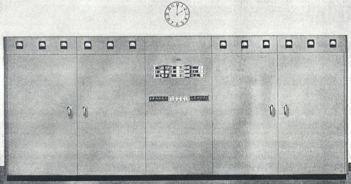
Engineers responsible for international operations, whether communications or short wave broadcast, will be especially interested in the care and attention given to the design of the Gates HF-20, twenty thousand watt transmitter. - Emphasis is on trouble-free operation, top performance in all climates, and complete absence of trick circuits and complicated mechanical tuning mechanisms.

Ease of installation-straightforward circuit design-100% air cooled- continuously variable except final tank-new low cost tubes-duplicate high voltage power supplies-and three models to choose from-are a portion of the HF-20 story.

FOR ALL MODES OF HIGH FREQUENCY TRANSMISSION

(20 kw, 4-22 mc)

In Gates HF-20 series twenty thousand watt transmitters three types are offered for short wave. These are:

Model HF-20B, a complete 20 kw short wave broadcast transmitter.

Model HF-20BX, the same as the HF-20B but with high speed telegraph, and provision for frequency shift keying adaption.

Model HF-20TX, a 20 kw telegraph transmitter only.

All models are very similar other than coil arrangement, and the elimination of the audio section in the case of the HF-20TX telegraph model.

CONSTRUCTION - Five cubicles join together to house the 20 kw radio frequency, audio frequency, protective and power supply units. The only external components are the two main power transformers, modulation transformer and reactor. These units are oil filled and may be installed either in the building or on a protected platform outside the building. The transmitter is dead front, and all front doors may be opened without disrupting the carrier. No inter-cubicle cabling is required when installing. Each of the five cubicles is completely assembled and wired. These cubicles bolt together speedily. At the base of each cubicle are barrier terminal boards; and wiring of all cubicles together for an operating transmitter is accomplished by means of short jumpers between these terminal boards. Floor space, exclusive of external units mentioned above, is 210" wide, 78" high and 49" deep. Door swing of 40" should be allowed for both front and back doors. Finish is in hand rubbed medium gray with trimmings in chrome, brushed aluminum and anodized black.

OSCILLATOR - A quickly detachable unit of the transmitter. A Colprits oscillator and a low powered first IPA stage tune the entire 4-22 mc band from the front panel. Four crystal positions, all temperature controlled, assure 0.005% frequency stability. Provision is also made for attaching a frequency shift keyer and an external variable frequency oscillator, where desired.

GATES 20 KW HIGH FREQUENCY TRANSMITTERS

RADIO FREQUENCY - Including the oscillator, there are five stages. The second IPA-doubler is a 6146 tube self-neutralized, the RF driver a pair of 4-250A tubes self-neutralized, and the final power amplifer contains four 3X2500F3 tubes in push-pull parallel. On short wave models, output is balanced into a 300-800 ohm line. On broadcast models, output is from 50 to 270 ohms, as ordered. The entire operation is continuously variable from the front panel on the short wave models, except the power amplifier tank circuit. For this service, Gates has developed the latch-on tank coil system and tank coils may be changed in a matter of seconds, eliminating all complicated tuning and band change mechanisms in the high power stage. Veeder counter type dials are used on all variable coils for split turn logging for frequency change. Of particular importance is the use of the thoriated tungsten filament 3X2500F3 tubes in the power amplifier, assuring long tube life and very low noise.

AUDIO FREQUENCY - Has four stages with push-pull parallel Class E 3X3000A3 tubes as modulators. Feedback is employed as an adjunct for improved noise reduction and less distortion. However, the HF-20 series transmitters will meet all acceptable standards without feedback. This means that feedback is not employed as a substitute for component size but, instead, to further improve the excellent performance possible without feedback.

METERING - No multi-metering is employed, and a full meter complement is supplied to measure all necessary circuits both for tune-up and general operation. Individual plate current meters are provided for each of the power amplifier and modulator tubes.

PROTECTION - Again Gates engineers have provided protection to the point that no power consuming circuit of importance has been overlooked. Primary thermal breakers are inserted in all main primary lines. Individual supervisory overload relays are incorporated for, not only the transmitter main overload, but also for separate protection; exciter failure, air failure, RF driver, power amplifier, audio driver and modulators. Included are secondary relays for door interlock and air cooling interlock. Automatic condenser discharge relay switch immediately discharges the main filter capacitors when the door interlocks are disengaged.

RECYCLING - Automatic recycliug relay controls automatically where the carrier is disrupted, and attempts to reset the carrier four times before remaining off. As many times carrier interruption is caused by static discharges across the transmission line or tower base, this recycling feature is indispensable.

POWER SUPPLIES - Five major power supplies deliver plate and bias voltage to the HF-20 transmitter. Featured are the two complete high voltage supplies. One is used for the radio frequency power amplifier and the other for the modulators. The resulting almost perfect regulation is quickly recognized by the engineer. Likewise, in case of failure of one power supply, the remaining one can be bussed in, operating the transmitter on reduced power until repairs are made. Each of these power supplies are full wave, three phase, six tube supplies. Other individual supplies provide modulator bias voltage, power amplifier bias voltage and intermediate voltage for driver stages. All power supplies are generously protected by circuit breakers, overload relays, etc. (see PROTECTION above).

KEYER - In the HF-20BX and HF-20TX models, electronic keying is through an 812A tube so biased that with key closed no current is drawn. This operates in conjunction with the oscillator and IPA doubler stage. Keying speeds up to 400 WPM are possible, with excellent square top wave form.

TECHNICAL SPECIFICATIONS
Frequency Range 4-22 mc standard HF-20 models. May be provided to 2 mc on special order
Power Output 20 kw at 100% modulation 2-18 mc. From 18-22 mc, 16 kw.
Telegraph models may be operated at slight excess to above ratings, depending on mode of keying
Power Input Key down, no modulation, approximately 37 kw.
Average program modulation, approximately 43 kw. At 100% modulation, approximately 55 kw
Input voltage 230 volt, 3 phase, 50 cycles (60 cycles available where stated).
Other primary voltages on special order
Input Impedance 600 ohms at +14 dbm
Output Impedance 300-800 ohms into balanced line for high frequency models
Crystals Provision for four in two ovens, selectable from front panel. 0.005% accuracy
Response ±1.5 db 50-10,000 cycles
Noise 55 db or better below 100% modulation
Distortion 3% or better 100-5000 cycles. 4% or better 50-7500 cycles
Keying 400 WPM or less, as required. Also provision for frequency shift keying
Size 210" wide, 78" high, 49" deep. Door swing 40"
Weight Approximately 23,000 lbs. packed
Cubage 720
Specifications may change without notice

TUBE COMPLEMENT
RF stages AF stages and modulator Rectifiers
Number Type Number Type Number Type
4 3X2500F3 4 3X3000A3 12 673
2 4-250A 2 845 2 866A
1 6146 2 807 4 8008
2 6AG7 2 6J7


THIS TYPE OF TRANSMITTER IS INSTALLED IN THE FOLLOWING COUNTRIES

ITU Country
ITU Country
flag MOZ MOZ MOZAMBIQUE