MARCONI B 6124

GENERAL DESCRIPTION


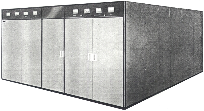
250 kW H.F Broadcasting Transmitter Type B 6124

photo Marconi B 6124 FEATURES
GENERAL DESCRIPTION

Only four vacuum tubes are used in the 250kW H.F Broadcasting Transmitter Type B 6124, two being employed in the modulator, one in the penultimate r.f stage and one in the final r.f. In addition, all tubes, except the penultimate r.f which is water cooled, employ self-condensing boilers thus retaining the advantages of vapour cooling in the tube design whilst replacing bulky steam piping by compact and convenient water cooling circuits.

A complete frequency change is achieved in less than 20 seconds, the transmitter responding to a single control operation, which can be made from the front panel or from a remote position.

The transmitter consists of two cabinets separated by a walk-through gangway permitting access to an enclosure situated behind the transmitter containing large iron-cored components, smoothing circuits and main h.t rectifiers. The walk-way also provides access to the r.f and modulator cabinets in addition to the access provided by doors on the outside of the cabinets.

The B 6124 transmitter is designed for operation under trapezium modulation conditions. Such operation requires the use of an external clipping amplifier (the B 6950 is designed for this purpose). The low-frequency distortion of the trapezium waveform, which is inherent in the high-power modulation components, has been eliminated by incorporating suitable phase correction circuits in the audio and modulator circuits. Also the power rating of the final r.f modulator stage allows for the increased levels of trapezium modulation. The block diagram shows the three vacuum tube stages and their associated drives and power supplies. Reference to the schematic block diagram will make the following description clear:

R.F drive

The transmitter can be driven from either an internal or an external drive source. This allows flexibility in drive arrangements to accommodate customer preferences.

Tuning

The low-power wideband r.f amplifiers use solid-state devices and require no tuning over the full frequency range of the transmitter. The single-ended, one tube penultimate and final r.f amplifiers use the minimum number of tuning controls, and moving parts are designed with low mechanical inertia to provide fast action with reliability of operation.

The servo systems used to control the tuning motors are of proved design and have been used successfully in Marconi communication transmitters.

R.F circuits

The r.f amplifier employs two vacuum tube stages preceded by a wideband transistorized amplifier. The conservatively rated transistorized r.f amplifier has a frequency range of 3.95 MHz to 26.1 MHz.

The intermediate amplifier uses a water-cooled tetrode, type 4CW25000A. The output of this stage is modulated to allow non critical adjustment of drive level to the final r.f amplifier which employs a tetrode type TH537 operating with grounded cathode connection. Amplitude modulation is applied to both the anode and screen of the valve. The tuning and coupling networks are designed to match into a 50 ohms unbalanced load.

The inductors in the output stage are switched to give the required values to cover the range and tuning is effected by variable vacuum capacitors. Inductors, switch contacts and capacitors are water cooled.

Wideband couplers are used to monitor power output and v.s.w.r. The power is automatically removed if the v.s.w.r exceeds the safe maximum value. Unwanted radiations are reduced to the internationally agreed level by harmonic filters. When the transmitter is required to operate into balanced transmission lines an external balun can be supplied. This converts from the 50 ohms coaxial mode to the balanced mode and matches to the optimum impedance of 300 ohms.

Modulator

The modulator uses solid-state amplifiers followed by two tetrodes in a push-pull Class B system. The modulation transformer and reactor are designed to handle trapezium modulation with a minimum of tilt and over-shoot. Precorrection of the clipped speech input is applied to meet the specified performance, when an external optional clipper is used.

The modulator driver transistorized amplifiers are effectively protected. Overall negative feedback with a 6 dB stability margin is used to ensure low audio-frequency harmonic distortion and hum level.

Power supplies

All supplies are mounted in the main transmitter cubicle with the exception of the main h.t, which is in the enclosure at the rear. Vacuum contactors are included in the main h.t rectifier to provide reduced voltage when tuning the transmitter.

All rectifiers employ silicon diodes tested to withstand direct short-circuits.

It is sometimes necessary to supply transmitters with power from on-site generators, either as a main source, or as a standby in case of failure of the national supply. In such cases, where the transmitter forms the major portion of the load, certain special conditions are imposed upon the performance required from the generator. MCS Ltd will be pleased to advise on the correct specification of generators intended for use with these transmitters.

Controls

Solid-state devices are used in the control sequence and overload protection circuits. These have a very high noise immunity and relatively slow operational speed to tolerate the high level switching surges associated with high-power transmitters.

The transmitter can be started or stopped by the operation of a single contact either locally or remotely. Alternatively, from the local control position the transmitter can be started in three stages:
1) Cooling and filaments.
2) Auxiliary and bias voltages.
3) Main h.t applied at reduced and then full voltage.
The control circuits incorporate proving sensors to establish that all three phases of the mains are present and are within the permitted tolerance.

Protection

When a short period mains failure of up to three seconds occurs the transmitter is restarted after the reapplication of mains power without going through the normal starting sequence. Intermittent faults on the transmitter or feeder system are detected and cause the removal of transmitter h.t power. A recycling overload system is incorporated which reapplies power and then goes to a 'lock out' condition if the fault is of a persistent nature.

In the event of an internal flash-arc in any of the final stage tetrodes, high-speed switches are used to extinguish the arc rapidly, and so protect the tube from high levels of follow-through current both from the supply and from the energy stored in system reactances. The vacuum switch is so positioned in the system that vacuum tube protection is achieved without subjecting the main supply and associated components to the high fault levels which are so often an undesirable feature of 'Crowbar' flash-arc protection systems. 'Tell-tale' lamps are incorporated to show the status of the equipment. Fault indicators continue to show the location of the fault after removal of h.t power. Resetting is a manual operation.

Safety devices

To ensure the safety of all personnel a system of mechanical and electrical interlocks is used. With the main isolator open, access to all parts of the transmitter is available with complete safety. When closed, filaments, fans and control circuits can be powered with certain doors open.

However, where voltages over 50 V a.c are applied, covers and warning notices are fitted. Before high voltages can be applied, all doors have to be locked and the keys returned to an interlock panel. When all keys are located the earth switch and power switch can be operated, allowing power to be switched on. While power is on it is impossible for a key to be released.

A separate, key interlocked, main h.t earthing switch is provided to earth the h.t rectifier and d.c filter components.

Construction

For ease of installation and transport the transmitter is built up from two cubicles, each of which dismantles into two sections which can be conveniently handled. For the same reason each of the sections is built on a robust steel base. The main h.t transformer, modulation transformer and modulation reactor are oil-filled components and stand in the rear enclosure.

In a typical installation the main air fans, together with the airfilter, water pump, water tank and heat exchanger, are mounted above the main transmitter. However considerable flexibility in the positioning of these items is possible to suit particular requirements.

Cooling system

The high-power vacuum tubes are vapour phase cooled but are so constructed that the vapour condenses within the boiler itself. This ensures that the advantages of vapour cooling for the optimizing of tube performance are preserved while restoring the convenience of compact water pipe runs from the boiler. Inductors, switch contacts and capacitors are water cooled. Distilled or demineralized water is used as a coolant and is pumped in closed water circuits which include expansion tanks and an external heat exchanger. Normally the heat exchanger is air-blast cooled. Alternatively, a water/water heat exchanger may be more suitable. Both the type of heat-exchanger, and its position in relation to the transmitter can be chosen to suit the circumstances. An air-cooling system requires high pressure air to cool the seals of the modulator, penultimate r.f and final r.f tubes. In addition both the main transmitter cubicle and the h.t enclosure are cooled by low-pressure air. An external roll-type air filter is required (in which a motor automatically winds on the filter element when the pressure drop through the filter exceeds a certain level) or alternative filters of a suitable type. The air-cooling systems are protected by pressure switches and thermal overloads and a hold-on circuit ensures adequate cooling after shut-down.

TECHNICAL SPECIFICATIONS
Power output 250 kW carrier power to transmission line at nominal mains voltage
Working frequency range Continuous through each of the following bands
MHz
3.950 to 4.00
4.750 to 5.060
5.950 to 6.200
7.100 to 7.300
9.500 to 9.775
MHz
11.700 to 11.975
15.100 to 15.450
17.700 to 17.900
21.450 to 21.750
25.600 to 26.100
Time for frequency change Less than 20 seconds
Type of transmission Amplitude modulation, d.s.b (CCIR classification A3)
Modulation High-level Class B
R.F output load impedance 50 ohms coaxial with a max v.s.w.r of 2:1. An external balun is available for connecting to 300 ohms balanced transmission line.
R.F harmonics and spurious radiations The mean power of any spurious emission will not exceed a value of -60 dB relative to unmodulated carrier. (ITU Radio Regulations, 1968 Ed, Appendix 4.) For harmonics etc, above 40 MHz the level is 20 dB below this figure, i.e 80 dB down on carrier (corresponding to 2.5 mW)
Drive A synthesizer drive is used which can be mounted externally if required
Frequency stability With standard synthesizer, 5 parts in 107 per month. Higher stability versions available
Carrier shift Less than 5% amplitude between 0 and 100% modulation measured at 400 Hz. Reactance of power supply, assumed at 1%, included in this figure
Audio input impedance 600 ohms, balanced (nominal)
Audio input level control 19.5 dB in 0.5 dB steps by front panel controls
Nominal audio input level With the front panel control set at centre position a preset attenuator allows 40% modulation to be obtained from a 400 Hz tone at any level from -5 dBm to +10 dBm
Audio frequency response ±1.0 dB, 50 Hz to 7.5 kHz, relative to 400 Hz at 75% modulation, without phase correction for trapezium modulation
Modulator phase and frequency characteristic Tilt and overshoot on the trapezium waveform produced are less than 5%, with the transmitter modulated 95% by 200 Hz to 3 kHz test signals from an audio peak clipping amplifier
Audio frequency harmonic distortion Less than 2.5%, 50 Hz to 7.5 kHz, up to 50% modulation
Less than 3.5%, 50 Hz to 7.5 kHz, up to 95% modulation
Noise and residual modulation At least 60 dB (or 70 dB when weighted according to CCITT Rec. P53B network) below the level corresponding to 100% modulation by a sinewave signal at 400 Hz
Monitoring Couplers on the output circuits supply:
  1. The r.f envelope monitor
  2. Approx. 10 V r.f into 50 ohms (unbalanced) at carrier level for external monitoring
  3. An a.f monitor providing an output at 40% modulation, which can be adjusted between approx. 5 dBm and 0 dBm into 600 ohms balanced
Operating conditions Ambient temperature : 2°C to 50°C
Maximum altitude : 2300 m (approx. 7500 ft)
Maximum humidity : 95%
Transmitter rating
  1. Instantaneous modulation capability : 100% sinewave modulation, 50 Hz to 7.5 kHz
  2. Thermal modulation capability : 95% trapezium modulation at frequencies from 200 Hz to 3 kHz for ten minutes per hour, and 95% sinewave modulation at frequencies from 100 Hz to 7.5 kHz during the intervening fifty minute periods.
    Alternatively : 100% sinewave modulation at frequencies from 100 Hz to 7.5 kHz, continuously
Note : The continuous tone rating of the transmitter is chosen to be in excess of that sustained by normal programme conditions, whether unprocessed speech or music, or speech processed to give trapezium modulation
Incoming power supply All auxiliary circuits 380 V or 415 V, 3 ph, 4-wire, 50 Hz. (Equipment for 60 Hz can be supplied if specified with order.) The main h.t rectifier equipment is arranged to conform to user requirements (normally 3.3 kV or 11 kV, 3 ph)
Variation of supply voltage ±10% for auxiliary circuits.
For the main h.t supply, the transmitter is provided with taps in order to compensate for the difference between the normal supply voltage to the transmitter, where this differs from the nominal voltage. The range of adjustments is ±10% in 2.5% steps. Having selected the correct tap setting the transmitter will remain operational throughout short-term supply voltage variations of +5%, -10% with respect to the normal value. In addition full performance (except power output) will be maintained with variations of ±2%
Variation of supply frequency ±1% reference nominal frequency
Overall power factor of equipment Better than 0.9
Overall power consumption and efficiency
Power output (kW)
Power input (kW)
Efficiency %
Carrier

250
455
55
Sinewave
40% Mod

264
528
50
Sinewave
100% Mod

355
710
50
Trap
95% Mod

414
795
52.0
A carrier shift of 2.5% amplitude at 100% modulation is assumed
Specifications may change without notice

TUBE COMPLEMENT
RF stages AF stages and modulator
Number Type Number Type
1 4CM300,000GA or TH 537 2 TH 583
1 4CW25,000A


THIS TYPE OF TRANSMITTER IS INSTALLED IN THE FOLLOWING COUNTRIES

ITU Country
ITU Country
flag CYP CYP CYPRUS flag NIG NIG NIGERIA
flag SUI SUI SWITZERLAND flag TWN TWN TAIWAN
flag UAE UAE UNITED ARAB EMIRATES flag G G UNITED KINGDOM