MARCONI BD 252

GENERAL DESCRIPTION


50 kW Air-cooled High Frequency Broadcasting Transmitter Type BD 252

photo Marconi BD 252 
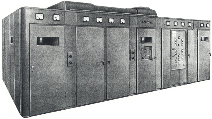
THE TECHNIQUE of air cooling as applied to high-power transmitters holds distinct advantages over other cooling methods and results in the production of compact, economic and comparatively simple equipments designed to give a high-fidelity transmission.

An entirely new system of construction, based on a standard size light alloy panel, is used both for the enclosure and for the free-standing cubicles. This greatly simplifies the task of erection.

Unit construction is employed and the units, which are all of small size, are built into two parallel rows running from back to front of the enclosure with wide passageways on either side.

Air-cooled valves are used in all stages. The cubicles containing the valves are hermetically sealed and form an integral part of the air ducting system. All unpleasant noise has been eliminated by using large area ducts and a low speed fan.

The class B modulator is driven by a cathode follower which enables up to 26 db of negative feedback to be applied. The AF filters normally associated with modulation transformers have been eliminated.

Rapid retuning by means of electrically operated circuits controlled from the front panel. Any one of six pre-selected frequencies can be set-up by a single operator in three minutes.

The new type HT rectifier uses six small single rectifier elements. Grid control is used and the unit retains most of the features of the single bulb rectifier with the added advantages of simplification, small size, economy of cost and ease of replacement.

A high overall efficiency is obtained by using thoriated tunsten valves and the latest circuit techniques.

Cathode driven circuits in the penultimate and final RF stages reduce phase distortion and eliminate neutralising adjustments.

A low hum level is achieved by Scott connecting the filaments of the high-power stages.

The small sized high-power valves can be manhandled without lifting tackle and each valve is mounted on extensible runners so that it can be withdrawn into the passageway and transferred to a valve trolley.

Maintenance is made easy by the excellent accessibility. All control circuits operate from a 50 V supply and so can be checked without applying mains power. A special circuit is provided for testing the overload relays.

Ease of operation. A mimic diagram containing anode and grid meters for all stages facilitates tuning. All supply push-buttons, together with overload indicator lamps are mounted on the central control panel.

The built-in cathode-ray monitor can be used for checking rectifier output, LF and RF wave forms and modulation diagram.

Parallel operation. Two or more transmitters can be operated in parallel without modification.

Compact layout. Only the large oil-filled components and the extractor fan are mounted outside the enclosure.

TECHNICAL SPECIFICATIONS
Power rating 50 kW up to 17.95 Mc/s. Capable of 100% modulation
Frequency range 5.95-26.1 Mc/s (50.4-11.5 m)
Frequency stability Better than ±20 c/s
RF harmonics Better than 57 db below the fundamental
AF response Level within ±1 db between 50 and 7500 c/s, and ±2 db between 30 and 10,000 c/s. Measured with reference to 60% modulation at 400 c/s
AF harmonics 3.5% from 30 to 10,000 c/s
2.5% from 100 to 5000 c/s at modulation depths up to 90%
Noise level At least 60 db unweighted and 75 db weighted, below 100% modulation
Input level 1 mW into 600 ohm for 100% modulation
Output impedance 330 ohm balanced, maximum standing wave ratio 1.4 to 1
Power supply 380-440 V Three-phase, four-wire, 50 c/s AC mains
Voltage regulation ±5%. Frequency tolerance ±2%
Phase variation within 1% of mean
Power consumption 194 kW at 100% mod. Efficiency 38.4%
Dimensions Height
8 ft 6 in.
(2.59 m)
Width
20 ft 6 in.
(6.25 m)
Depth
18 ft 3 in.
(5.56 m)
Specifications may change without notice

TUBE COMPLEMENT
RF stages AF stages and modulator
Number Type Number Type
? ? ? ?


THIS TYPE OF TRANSMITTER IS INSTALLED IN THE FOLLOWING COUNTRIES

ITU Country
ITU Country