NEC HFB-7847

GENERAL DESCRIPTION


TYPE HFB-7847 50 kW SHORT-WAVE BROADCAST TRANSMITTER

GENERAL

photo NEC HFB-7847 NEC Corporation (NEC) has led the field in design, development, and manufacture of telecommunications systems and equipments for more than seventy years in japan. Its experience includes high-power TV, FM and medium-wave broadcasting equipments as well as shortwave transmitting equipment delivered to customers around the world. The performance record of this NEC broadcasting and transmitting equipment has won the acclaim of engineers and technician-experts who judge telecommunications equipment by its proven performance.
This brochure introduces NEC's Type HFB-7847 50 kW Short-Wave Broadcast Transmitter. Featured by its excellent performance, high efficiency and compactness, the Type HFB-7847 occupies less floor space and is superior in performance to any comparable equipment in the world. Its maintenance is extremely simple, and it may be operated as an unattended or standby transmitter due to its extremely stable performance.

All tubes and other circuit components are designed and tested for maximum operational life and efficiency to ensure stable operation.

FEATURES

Only Four Tetrode Tubes in Transmitter.
Four high gain tetrode tubes are employed in all, one in Modulated Power Amplifier, two in Modulator Amplifier and one in Exciter stage.

All Circuits of Solid State Except PA, MOD and Ex.
With use of solid state circuits, driving stage has been improved in compactness.

Very Low Maintenance Cost.
To ensure an absolute minimum cost for maintenance, this transmitter employs high-gain, long-life tubes and high efficient circuit for power amplifier. Compared with conventional 50 kW transmitters, the cost for maintenance of the Type HFB-7847 is very low.

Reduced Installation Cost.
Since blower for cooling is mounted in a cabinet the transmitter can be installed easily.
Thus installation is made with low cost.

Highest-Grade Performance
Performance of this transmitter meets CCIR recommendation. It can fully satisfy your most exacting demands, giving you internationally approved performance wherever your site is planned.

Easy Maintenance and Inspection
Maintenance and inspection are simplified and made easier by the logically arranged panel construction of this transmitter. Meters on the front panel permit quick and efficient operational routine checks, and eliminate the danger of accidentally contacting HT devices.

Complete Protection of Equipment and Personnel
To provide complete protection for the equipment and personnel, this transmitter incorporates all necessary protective relays and an interlocking device that enables it to be started only in a prescribed sequence. In addition, the safety devices, which are used to completely protect the operator from the danger of contacting HT parts, are designed in accordance with appropriate domestic and internationally sanctioned codes and methods.

IC Control Circuit
All auxiliary circuits such as auxiliary relay, delay relay, overload relay and recycling relay except heavy duty magnet contactor are of integral circuit, thereby achieving to promote reliability considerably because of the following improvements:
- less mechanical abrasion
- less heat radiation
- free from environmental influences such as dust and various poisonous gas.

A Vapor Cooled Tube is used which is Easy To Maintain and has a High Efficiency of Cooling.
The following advantages are obtained by using vapor cooled tubes in the final power amplifier and modulator:

(1) Distilled water (refrigerant) used in the vapor cooling system becomes steam in the boiler which houses the vapor cooled tube. It is then condensed into water in the condenser and fed back to the boiler. This is known as a self-circulating cycle. This system does not require external water supply or discharge, as is the case with ordinary water cooling systems. Installation and maintenance of the transmitter station is much simpler, since pipe, fined tube, pump, and pool are not required.

(2) The forced air cooling system, though simple in installation and maintenance, creates much noise from the air duct and the vacuum tube when this system is imployed in a transmitter station with a power output of as high as 50 kW, because it must handle large amount of wind volume and high wind velocity to cool the plate of the vacuum tube. Under the same conditions, the vapor cooling system creates hardly any noise at all during operation, since it has no element which will produce noise.

(3) The vapor cooled tube provides better cooling efficiency than either the forced air or water cooling system. It is durable against overload. Cooling capabilities per unit are:
Forced air cooling system: 20-60 watts/cm2 (wind volume 2 m3/min. kW plate dissipation)
Water cooling system: 40-100 watts/cm2 (water quantity 2/min. kW plate dissipation)
Vapor cooling: 50-150 watts/cm2

(4) Low pressure pipes can be used for a circulation system. The vacuum tube can be installed easily (simply insert it in the boiler).

Mimic Diagram
As seen in the picture, metering and indicators replating to each circuit are arranged on the panel printed by the simplified circuit diagram. Transmitter's ON-OFF control, pre-set frequencies change control, OLR indicator and metering and waveform monitor at each stage are all collected on this panel so that the transmitter can be operated, adjusted and checked with ease.

Mechanical Interlock
Mechanical interlock is provided to prevent the door from being opened by a key when H.T. is applied. Also, opening the door will mechanically ground H.T., hence maintenance work can be accomplished wihout the danger of H.T.

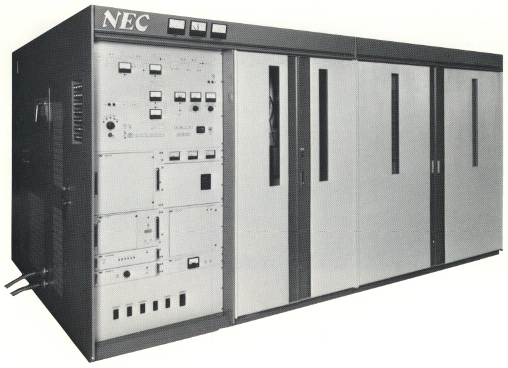
TECHNICAL SPECIFICATIONS
Rated Carrier Output 50 kW
Transmitter Output Capability 53 kW
Frequency Range and Frequency Changing Specified 6 pre-set frequencies within range of 3.2 to 15.6 MHz
Frequency Change Time Max. 3 minutes
Modulation system Final stage class B modulation system with simultaneous screen mod
Audio Frequency Response From 50 to 7,500 Hz. Flat within ±1 dB
From 30 to 10,000 Hz. Flat within ±1.5 dB
Audio Frequency Distortion Less than 3% at 95% modulation within a frequency range from 50 to 7,500 Hz
Noise Level Better than 60 dB. Unweighted for 1,000 Hz at 100% modulation
Carrier Shift Less than 3% for 100% modulation at 1,000 Hz
Carrier Frequency Stability ±1 x 10⁻⁶
Spurious Radiation Below 50 mW, complying with CCIR recommendation
Audio Input Level 0 dBm at 1,000 Hz for 100% modulation
Audio Input Impedance 600 ohms, balanced
Output Impedance 50 ohms, unbalanced
Modulation Capabilities 1,000 Hz at 100% modulation: 20 minutes
From 50 to 7,500 Hz at 100% modulation: 10 minutes
Overmodulation: Can withstand a level three times as high as the input level,
required to achieve 100% modulation at 1,000 Hz three times at each interval of 1 second for 2 seconds duration
Overall Power Factor More than 90%
Power Requirement AC 400 V, and 200 V ±2%, 3 phases, 50 or 60 Hz
Stable against voltage variations of ±10%
Ambient Temperature From 0° to 45°C
Cooling System Vapour cooling
Dimensions (a) Height: 2200 mm
(b) Width: 4400 mm
(c) Depth: 2800 mm
Specifications may change without notice

TUBE COMPLEMENT
RF stages AF stages and modulator
Number Type Number Type
1 4CV50,000E 2 4CV50,000E
1 4CX1500A


THIS TYPE OF TRANSMITTER IS INSTALLED IN THE FOLLOWING COUNTRIES

ITU Country
ITU Country
flag GHA GHA GHANA flag J J JAPAN