PHILIPS 8FZ 508

GENERAL DESCRIPTION


photo Philips 8FZ 508 
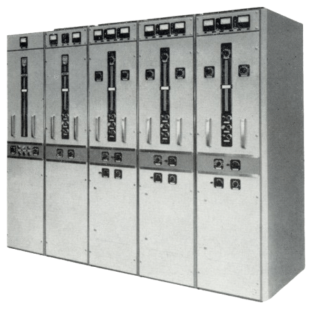
5 kW AM SHORT-WAVE BROADCAST TRANSMTITER TYPE 8FZ 508

The 5 kW short-wave transmitter type 8FZ 508 forms part of the standard series of Philips broadcasting equipment. Like the well-known 5 kW SW type SOZ 362 transmitter, it is particularly suitable for use in broadcast stations where non-specialized staff are employed. The most notable modernization, the replacement of rectifier tubes by silicon diodes, results in a low cost of operation, a great efficiency and a compact design.

Silicon diodes

Silicon diodes have a considerably longer life than rectifier tubes, so that their total cost is lower.

As the heater supply for the rectifier tubes can be dispensed with, the efficiency of the transmitter is increased and consequently lower power consumption is obtained. The more compact design permits polyphase rectification to be employed, which results in an improved power factor, less reactive power being required.

Silicon diodes are less critical with regard to ambient temperatures than mercury rectifiers. Control of ambient temperature by means of forced air draught is therefore unnecessary.

The diodes take up far less space than the conventional tubes. This has made it possible for a simplified version of the HT choke, which was originally installed in a separate housing, to be included in the power supply cabinet. The floor space required by the transmitter is thus reduced. There is no heating-up of filaments, so that the rectifiers can be switched on without any delay.

The backfire protection needed in mercury-arc rectifiers is dispensed with.

Further modernization

Further modernization is most notable in the components which have been the subject of considerable development over the last few years, particularly the switches, overload cut-outs and control relays.

The transmitter units are switched on and off by push button control. The holding circuits employed in the interlocking system offer improved facilities for remote control. The RF section and the modulator have retained their original circuitry, which has proved its soundness of design for several years now.

Some typical features are:
- Simple operation and tuning
- Ease of access and low maintenance cost
- Inexpensive installation and great flexibility in installation lay-out.

Frequency selection

The RF section of the transmitter consists of up to three RF units, depending on the number of frequencies required.

Each RF section is tuned to one out of seven specific frequencies in the 2.2-28 Mc/s range.

Change-over from one to another frequency is effected within seconds by switching from one pre-tuned RF unit to another.

RF section

The RF section consists of up to three RF units. Each RF unit is made up of an exciter, an intermediate stage and a power amplifier.

The exciter unit type SFE 133 is interchangeable. A selector switch enables it to be used either with a crystal-controlled circuit or, in emergencies, with a self-oscillating circuit. The transmitter can also be driven by an external VFO with a great frequency stability, to be ordered as an extra. The exciter unit has a frequency range of 2.2-28 Mc/s, divided into the following 7 subranges: 2.2.3.2 Mc/s, 3.2-4.7 Mc/s, 4.7-6.9 Mc/s, 6.9-10 Mc/s, 10-14.7 Mc/s, 14.7-21 Mc/s and 21-28 Mc/s.

The subranges are covered by using different plug-in anode circuit coils in the oscillator and buffer stages.

The intermediate stage of the RF unit is equipped with two type QQE 06/40 twin tetrodes in a push-pull circuit. The anode circuit is capacitively coupled with the output stage.

The power amplifier contains two air-cooled type QBL 5/3500 tetrodes, operated under class C conditions in a push-pull circuit.

Modulator section

The type SFV 169 modulation unit consists of push-pull stages throughout the chain. The power circuit is a two-stage voltage amplifier which includes a network for maintaining a phase relation suited to the application of feedback. The voltage amplifier is followed by a zero-gain cathode follower stage, which drives the grids of two air-cooled modulator power tetrodes. Feedback is applied to the grids of the input voltages amplifier from the anode circuit in the output stage via a resistor-capacitor network. This network has zero phase shift up to frequencies that are many times the highest modulating frequency. The input impedance of the modulator unit is 600 ohms.

Power supply section

The power supply unit type 8ED 500 comprises four different DC rectifier units, fully equipped with silicon diodes:
a single-phase full-wave rectifier for 170 V DC,
a three-phase half-wave rectifier for 600 V DC,
a three-phase half-wave rectifier for 800 V DC and
a three-phase half-wave rectifier for 4500 V DC

Construction

In the construction, special attention has been paid to efficiency and to use under conditions of tropical heat, extreme cold and considerable humidity. Each cabinet is fitted with drying lamps to prevent condensation occurring after the transmitter has been switched off. Only high-quality components are used, in order to increase reliability. The transmitter is equipped with the famous Philips tetrodes types QQE 06/40, QE 06/50 and QBL 5/3500. The useful life of these tubes is increased even further by conventional rating. The transmitter is stylishly finished, both at the front and at the rear. In addition, various protective circuits have been incorporated to guard staff and equipment from the consequencies of operational errors. A safety-gate switch fitted on the door of the power supply section switches off all high tensions (4500 V, 800 V, 600 V) as soon as this door is opened. No voltage can be applied to the output tubes until they are being cooled. The transmitter is completely screened and produces no troublesome radiation.

Mechanical design

The transmitter is composed of independent units which permit great flexibility of lay-out. A choise of many standard arrangements is possible, and the transmitter will suit almost any space available in existing buildings. Special arrangements can also be made to meet special circumstances.

The main units are the RF unit(s), the modulator unit and the power supply unit. The blower assemblies for the RF and modulator units, the power supply and modulating transformers, and the chokes and capacitors, are independent units and can be installed where space is available, e.g. behind the transmitter or in a separate room or cellar. Dummy panels to maintain a symmetrical outward appearance can be supplied if various components are installed behind the transmitter proper. The blower assemblies include air filters. These filters and the slightly higher pressure maintained in the cabinets prevent the ingress of dust. Extensive and detailed information in the instruction manual facilitates installation, operation and maintenance of the equipment. Installation is simple and requires no special tools or highly skilled personnel.

The name-plates and manuals supplied with the equipment are normally in English but other languages (e.g. Spanish) can be had on special order.

TECHNICAL SPECIFICATIONS
Carrier power output 5 kW for the carrier without modulation at nominal mains voltage and frequency
Frequency range 2.2-28 Mc/s in seven sub-ranges
Frequency stability 2.2-4 Mc/s: ± 20.10-6
4-28 Mc/s: ± 15.10-6
RF output impedance 600 ohms balanced at a max. SWR of 1 : 1.4. To special order 50 or 75 ohms unbalanced
RF harmonics according to CCIR recommendations
AF input impedance nominal 600 ohms balanced
AF input level 0 dBm ± 2 db for 100% depth of modulation by a 1000 c/s signal (0 dBm is 1 mW into 600 ohms)
AF response flat within ± 1.5 dB from 30 to 10,000 c/s reference 1000 c/s at 60% modulation
Non linear distortion less than 3 % from 50 to 10,000 c/s and 2% from 100-7000 c/s at modulation depth of 90%
Intermodulation two signals having frequencies between 5000 and 10,000 c/s and differing 180 c/s, each modulating the transmitter for 30%, will cause an intermodulation percentage of less than 2% for intermodulation products of the 2nd and 3rd order
Hum and noise level lower than -60 dB unweighted and lower than -70 dB weighted. Reference 1000 c/s at 100% modulation
Modulation capability 100% instantaneously and in the 50-10,000 c/s range
60% continuously
Carrier amplitude variation the average deviation of the carrier during modulation, calculated from power measurement made in a dummy load, is less than 5% up to modulation depth of 100%
Mains power supplies 3 x 380 V ±5%, 50 c/s or 60 c/s ±5%; four-wire mains: adaptation to other voltages is possible by use of an optional, separate auto-transformer
Power consumption (approximate, for a transmitter with one RF unit) at 0% modulation 11 kW
at 30% modulation 13 kW
at 100% modulation 16 kW
at stand-by approx. 2.5 kW
The consumption per additional RF unit at stand-by is approx. 1 kW
The consumption for the modulated transmitter is given for a modulation frequency of 1000 c/s. Average power factor 0.9
Ambient temperatures at sea level: 0° to 45° C
at 6000 feet: 0° to 35° C
Relative humidity up to 95%
Dimensions and weight (overall) for a transmitter with one RF unit height approx. 212 cm (84 in.)
width approx. 162 cm (64 in.)
depth approx. 87 cm (34 in.)
minimum floorspace 300 x 350 cm (10 x 12 ft.)
weight unpacked approx. 2500 kg (5500 lb.)

TUBE COMPLEMENT
RF stages AF stages and modulator Rectifiers
Number Type Number Type Number Type
2 QBL5/3500 (6076) 2 QBL5/3500 (6076)

3 QQE06/40 (5894) 6 QE06/50 (807)

1 OA2


1 E80L (6227)


1 EF91 (6AM6)


THIS TYPE OF TRANSMITTER IS INSTALLED IN THE FOLLOWING COUNTRIES

ITU Country
ITU Country