| GENERAL DESCRIPTION |
 Editorial note
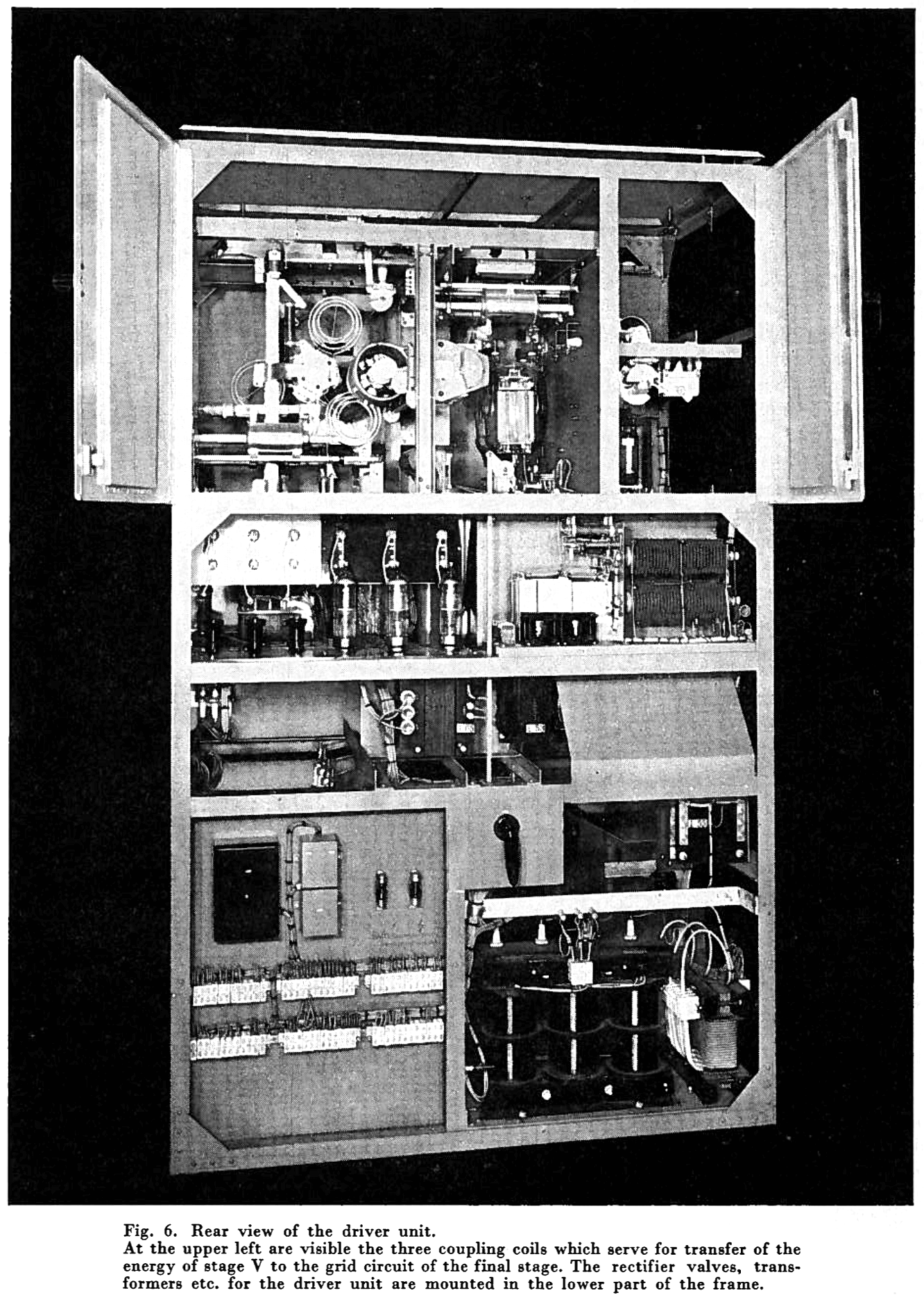
 2. The driver unit
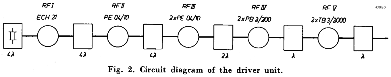
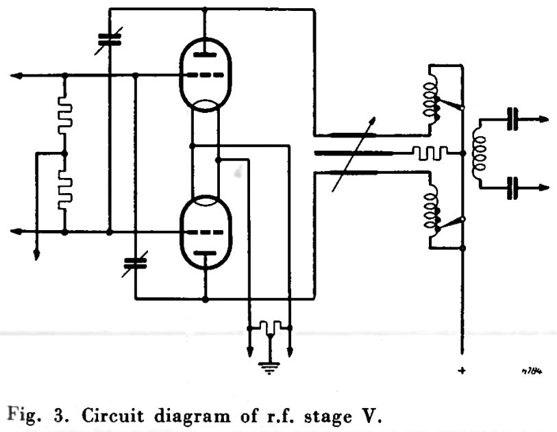
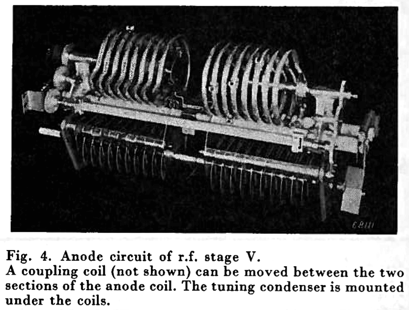 The r.f. stages IV and V which are mounted above the drawer are provided with forced air cooling so that, even at high ambient temperatures, the valves and circuits are adequately cooled. R.f. stage V is a class C balanced amplifier, the neutralization of which has been carried out in such a way that readjustment is not necessary for any change of operating frequency within the limits of the frequency range of the transmitter. In fig. 3 the circuit diagram of r.f. stage V is given, while fig. 4 shows the anode circuit of this stage. This anode circuit is tuned by short-circuiting parts of the coil and by means of a variable condenser. The coil consists of two sections between which a coupling coil can be moved. As a result of this construction the central spindle consists of two halves which are electrically connected with each other by means of contact discs and contact fingers. On the two central spindles are mounted a number of contact fingers which can thus be rotated in both directions resulting in short-circuiting a corresponding part of the coil. The anode circuit is inductively coupled to the final stage by one of three coupling coils which are mounted on a spindle. The required coupling coil can be rotated between the two halves of the anode circuit coil as already mentioned. The coupling coils are designed for connection to a symmetrical feeder with a characteristic impendance of 450 to 600 ohms.
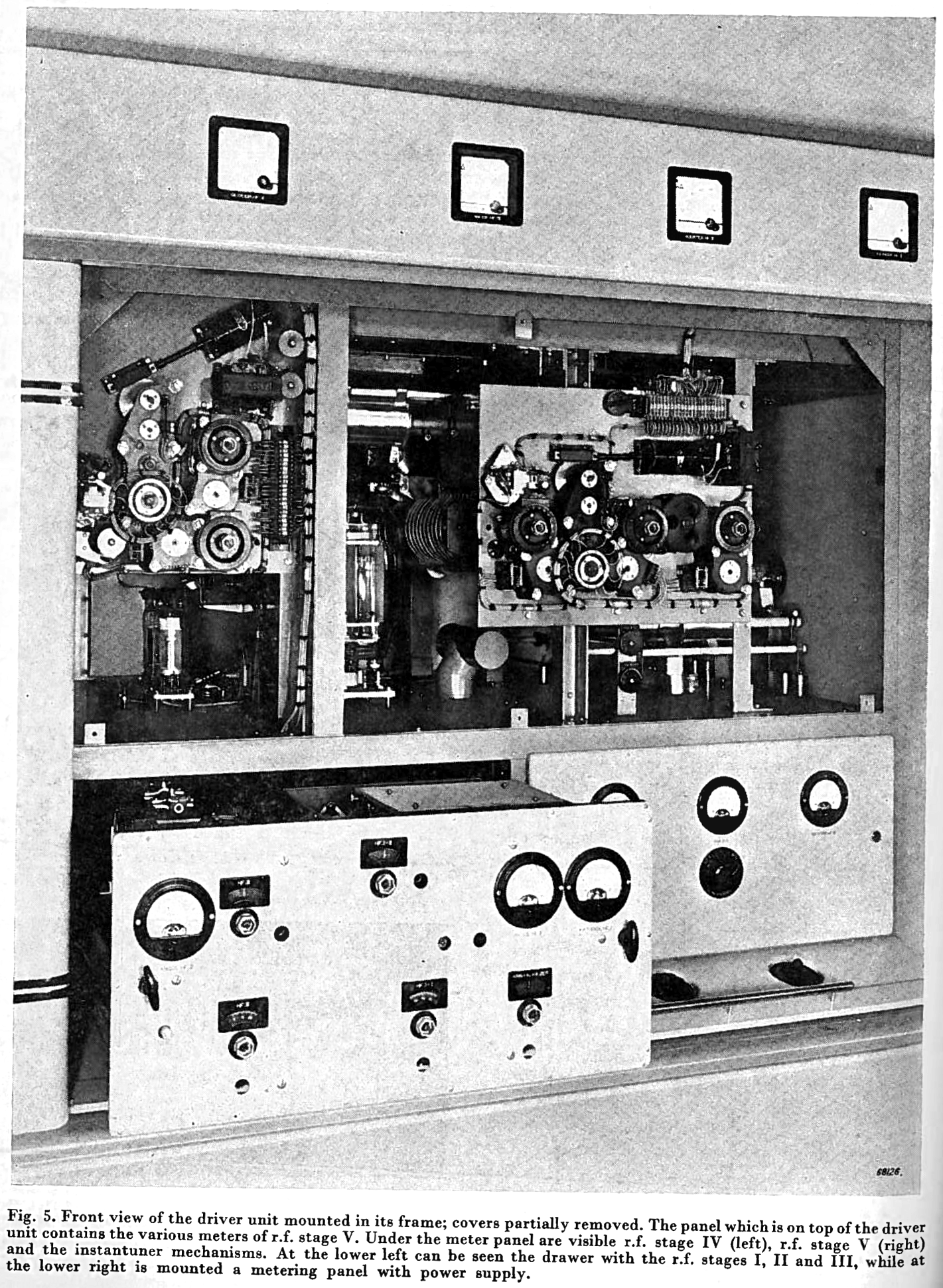
 As has already been stated, the condenser, the contactfingers for short-circuiting the coil of the anode circuit, and the coupling coils are adjusted by means of instantuners.
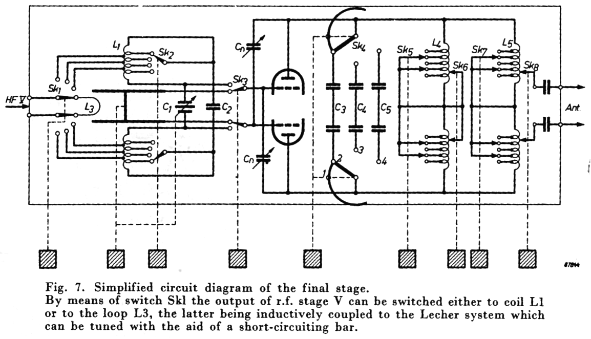 Fig. 7 shows the simplified circuit diagram of the final stage. The components which, after first being adjusted and then rotated to the desired position by means of instantuners, are each indicated by a character. The various main parts of the final stage are the grid circuit, the anode circuit and the valve assembly with the neutralizing condensers and the fixed tuning condensers.
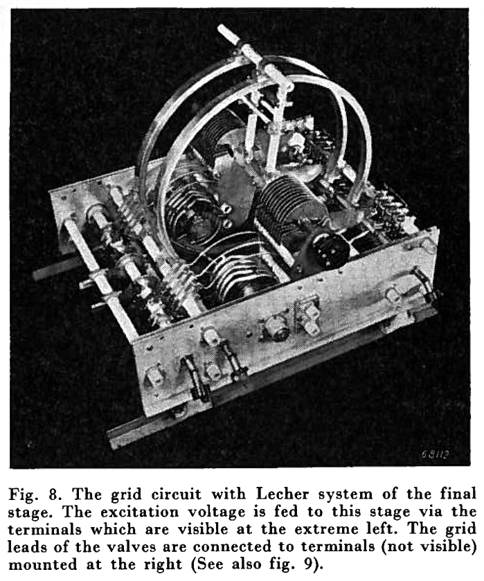 When the excitation voltage is fed to L1, one of three taps on the grid circuit can be selected with the aid of switch Sk1 in order to obtain correct impedance matching. For covering the entire frequency range with L1 and C1 the coil is provided with taps which can be selected by means of the switch Sk2. With the aid of condenser C1 the total frequency range is thus subdivided into smaller overlapping ranges.
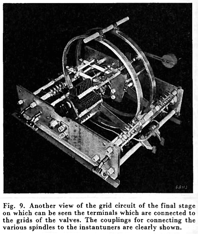 With the aid of switch Sk3 either L1 or the Lecher system is connected to the grids of the valves of the final stage. The coil L1 (which consists of two sections), the condenser C1 and the Lecher system form one unit. For practical reasons the Lecher wires are bent in a circular form. Since either the condenser C1 or the Lecher system is operated, the short-circuiting bridge of the Lecher system has been mounted, via two insulators, on the shaft of the condenser C1. This short-circuiting bridge can be rotated along the Lecher system over an angle of 360 degrees so that the insulators bearing the short-circuiting bridge can make one complete revolution. This has been accomplished by splitting the coil L1 as well as the condenser C1 into two identical parts between which the Lecher system is mounted. Short-circuiting of the coil and rotation of the contact fingers takes place in the same way as described for the driver unit. The Lecher system is made of a bent U-shaped metal profile one side of which serves as contact path along which the specially designed triple contact rotates. The construction of this contact will be dealt with further on.
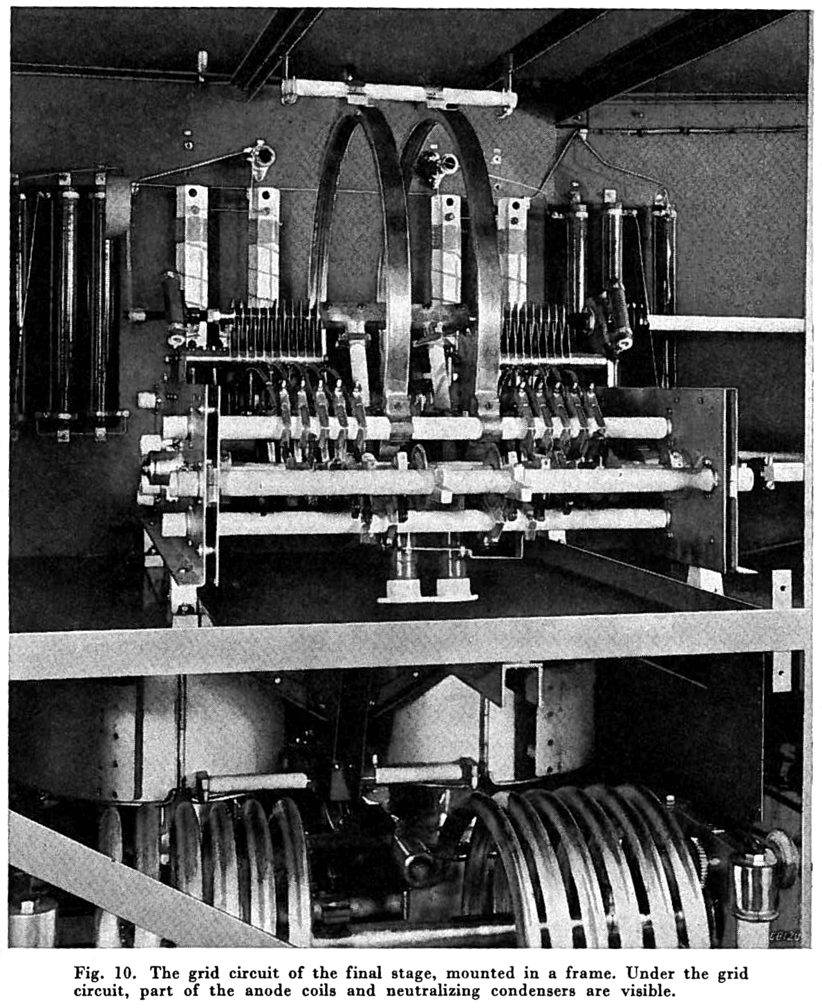 The total inductance of the circuit depends on the position of the switches Sk6 and Sk7, which are connected with the coils L4 and L5 respectively. The inductance of coil L4 can be varied continuously by means of switch Sk6, the inductance of L5 being variable in steps by means of switch Sk7.
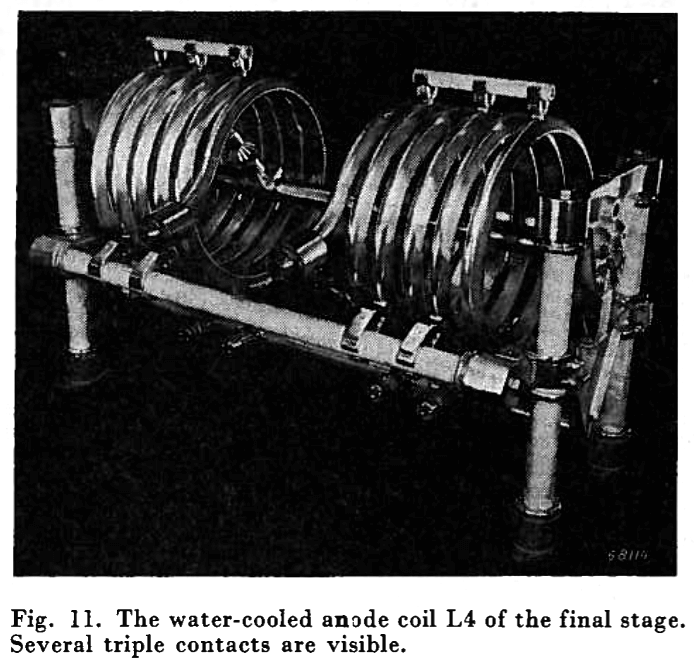 The switch Sk5 is used for short-circuiting in steps various parts of the coil L4 in order to prevent unwanted reflections.
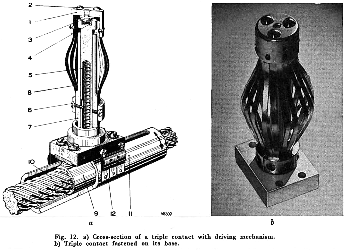 For this purpose a special triple contact has been applied which can be moved inside the coil. As expressed by the name this contact always rests on the contact surface at three different points and is designed in such a way that sufficient flexibility is obtained. The triple contact, as already mentioned above in the description of the grid circuit, is shown in fig. 12a and b. On top is mounted a bush (1) in which are riveted three silver contacts (2). Since bush (1) is supported by a spherical surface (3) and is centered in a triangular hole (4) a "hinge action" of the contact with respect to its support is obtained. The pin with the triangular hole is pressed upwards through the action of a spring (5) which also determines the contact pressure. The stroke of the pin is limited by means of a screw (6) and a slot in the pin. The maximum stroke is sufficiently large to cover all practical tolerances of the contact surface. In order to ensure a reliable current path from the "hinged" bush to the fixed part of the contact (7), these parts are connected to each other by means of latten copper strips (8) which does not impair the flexibility of the contact.
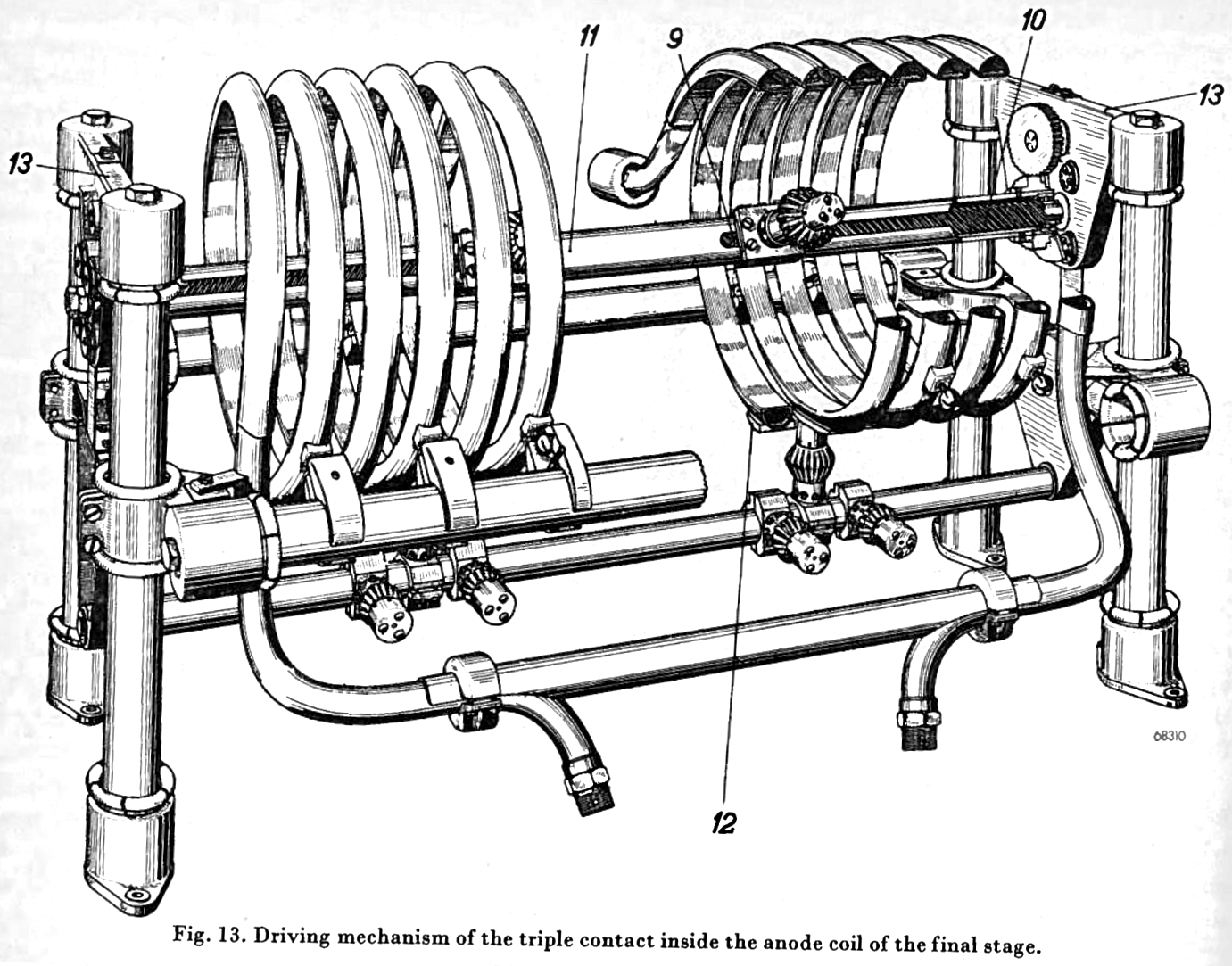
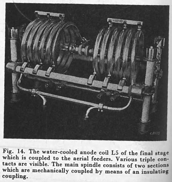 Fig. 13 shows the driving mechanism of the triple contact. A threaded bar (10), the pitch of which equals that of coil L4, is mounted rigidly to the above-mentioned end plates (13) of the coil. This threaded bar carries a bush (11) which is mounted on ball bearings. Rotation of the bush (11), which is provided with a slot for driving the threaded body (9), results in a combined axial and radial displacement of the triple contact which is mounted on the threaded body. The bush (11) is actuated via a gearing. Fig. 12a gives a clearer picture of the threaded body (9), the fixed threaded bar (10) and the slotted rotatable bush (11). Fig. 12a also shows the springs with the silver-alloy contacts (12) which are mounted on the movable bush for ensuring a dependable current path from the threaded body (9) and the triple contact, to the fixed part of the circuit.
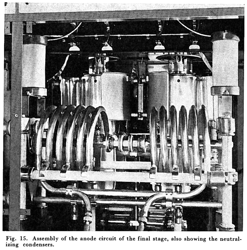 At the lower part of the supporting structure, bearings are provided for switch Sk5. This switch, which has four positions, consists of a metal shaft on which are mounted various triple contacts, 90 degrees apart. The mating fixed contacts of the switch which have the shape of blocks are welded to the coil.
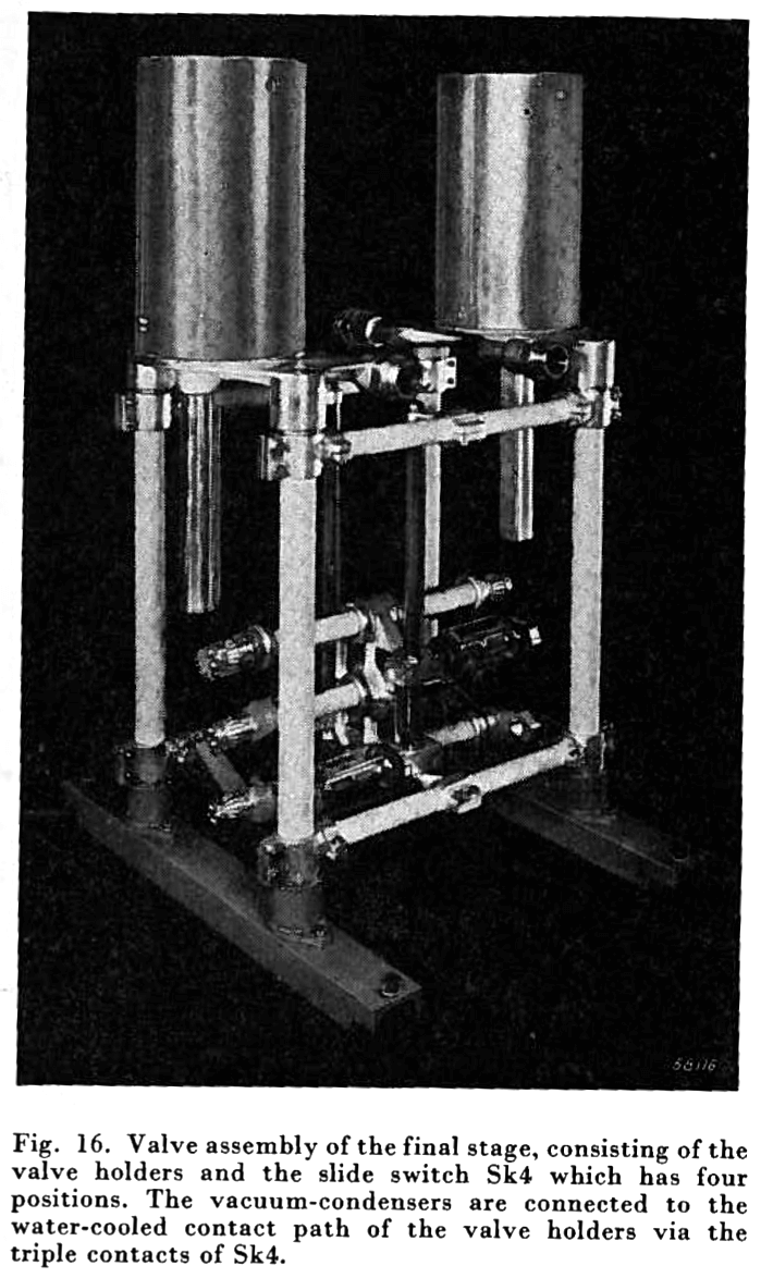 c. The valve assembly with the fixed condensers of the anode circuit
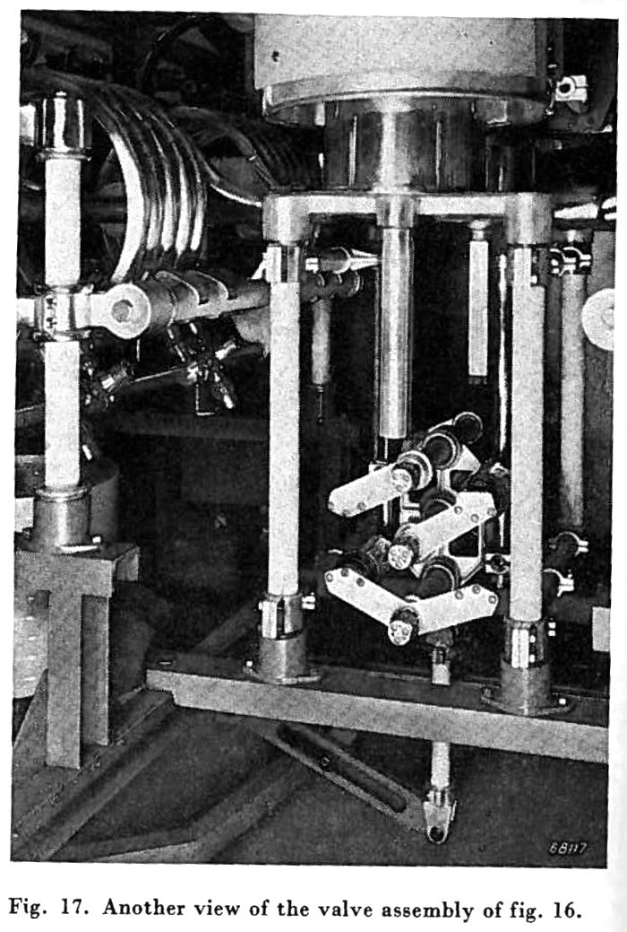 The variable neutralizing condensers (figs. 15, 17 and 18) are each formed by the outer surface of a valveholder which has the same potential as the anode, and by a corresponding metal cylinder surrounding the valveholder. and consisting of a fixed part and a variable part. The fixed part of this cylindrical jacket is connected with the grid of the other valve by means of strips (fig. 18), while the variable part can be rotated on a vertically mounted hinge thus forming the adjustable section of the neutralizing condenser.
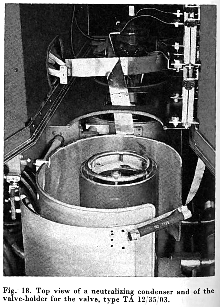 The input signal, arriving via a line with a characteristic impedance of 600 ohms is adjusted to the required value for 100 percent modulation (1,55 Volt r.m.s.) by means of an H-attenuator on the control desk.
 5. The 12 kV rectifier
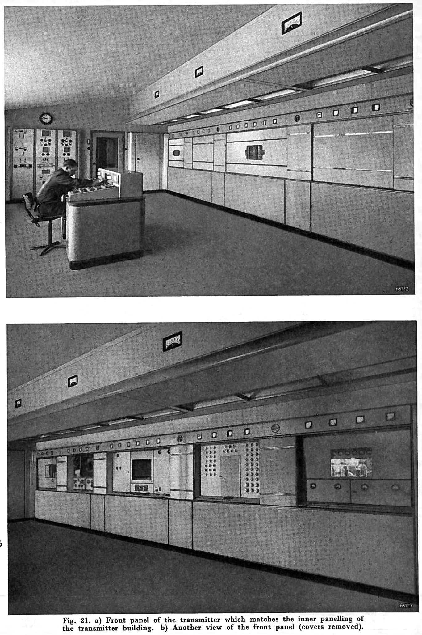 8. The control desk
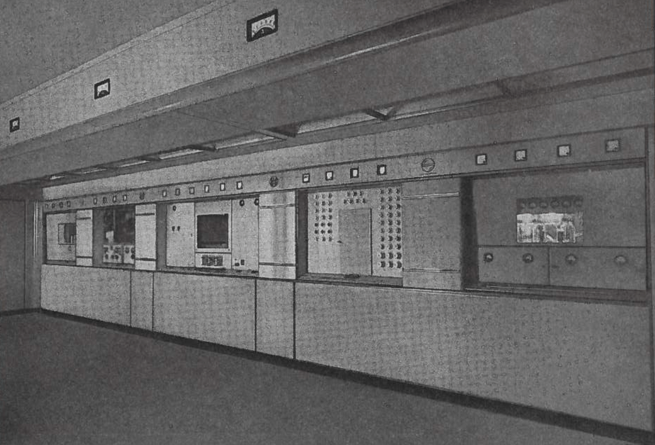
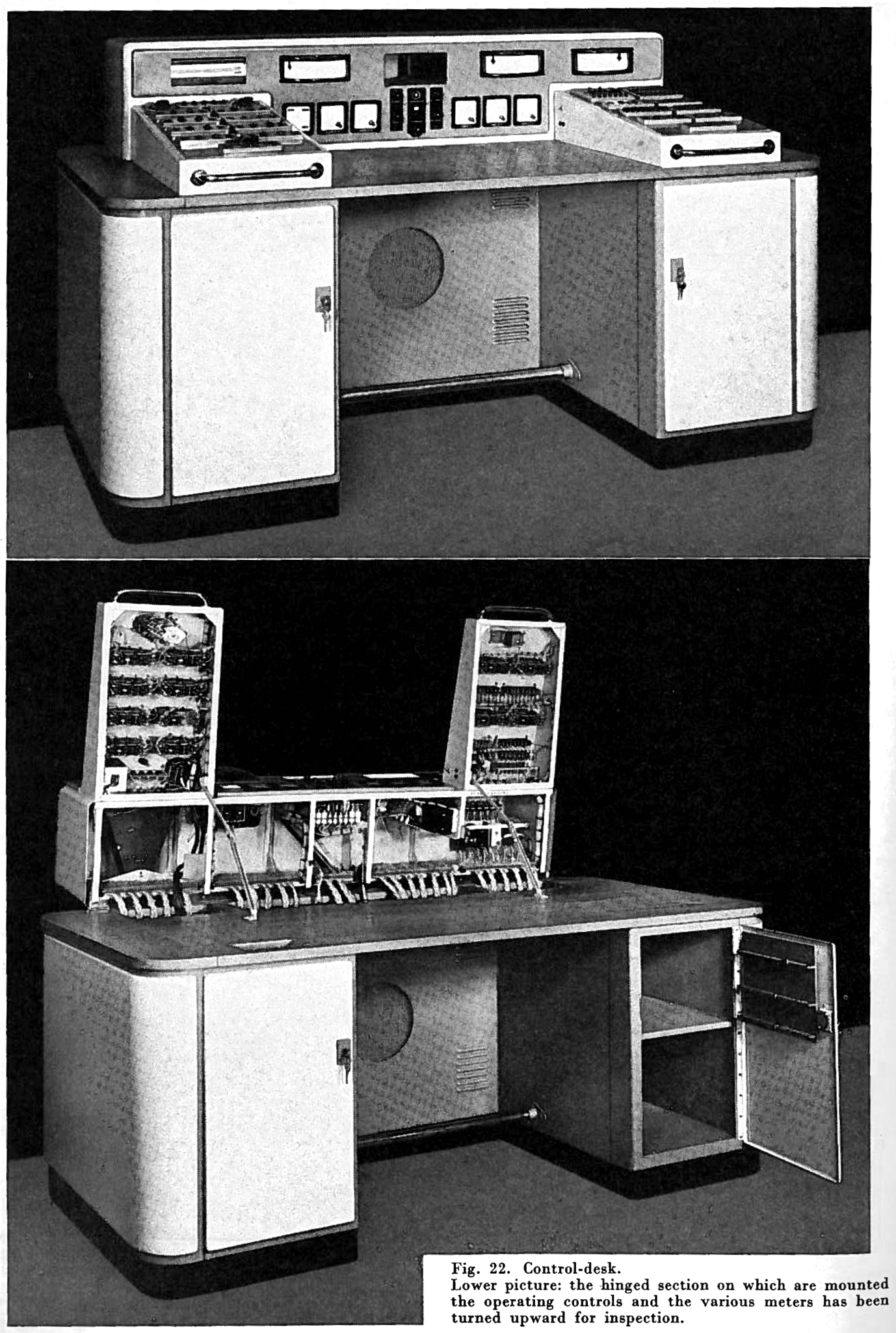
|
|
|
| TECHNICAL SPECIFICATIONS | |
| Frequency stability | The frequency stability easily meets the Atlantic City specifications. |
| Hum | Depending on the load of the various phases of the mains, the total hum of the transmitter with the modulator lies between -62 and -57 DB (with a modulation depth of 100 percent as reference level). |
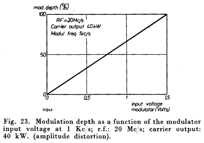
| Amplitude distortion | Fig. 23 gives the modulation depth as a function of the modulator input voltage, for a modulating signal of 1000 c/s, an output of 40 kW and an operating frequency of 20 Mc/s. |
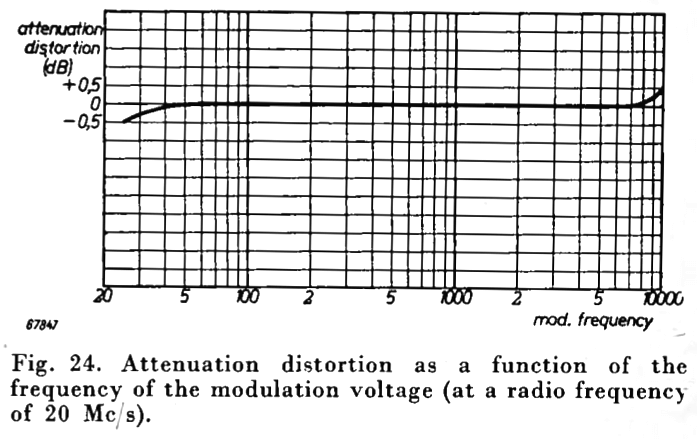
| Attenuation distortion | The attenuation distortion as a function of the modulation frequency at 20 Mc/s, with 1000 c/s modulation frequency as reference frequency, is given in fig. 24. |
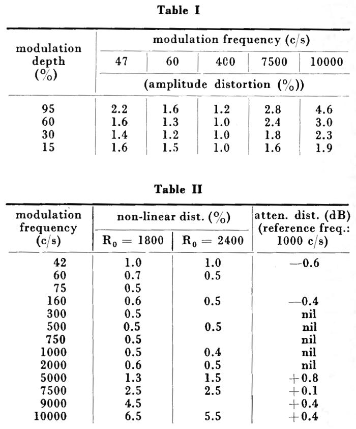
| Non-linear distortion | The non-linear distortion for an output of 40 kW and for an operating frequency of 20 Mc/s is given in table I. |
| Performance of the modulator | Table II gives the frequency distortion and the non-linear distortion of the modulator when loaded with 1800 and 2400 ohms respectively. These values hold for a modulator output power of 35 kW. |
| Harmonics | Harmonics radiation is well within the limits of the Atlantic City specifications. |
| TUBE COMPLEMENT | |||||
| RF stages | AF stages and modulator | Rectifiers | |||
| Number | Type | Number | Type | Number | Type |
| 2 | TA12/35 | 2 | TA12/35 | 6 | DCG5/30 |
| 2 | TB3/2000 | 4 | PB3/800 | ||
| 2 | PB2/200 | 2 | PB2/200 | ||
| 3 | PE04/10 | 2 | PE04/10 | ||
| 1 | ECH21 | ||||
| THIS TYPE OF TRANSMITTER IS INSTALLED IN THE FOLLOWING COUNTRIES | |||||
| ITU | Country | ITU | Country | ||
| HOL | NETHERLANDS | ||||