| GENERAL DESCRIPTION |
 Summary
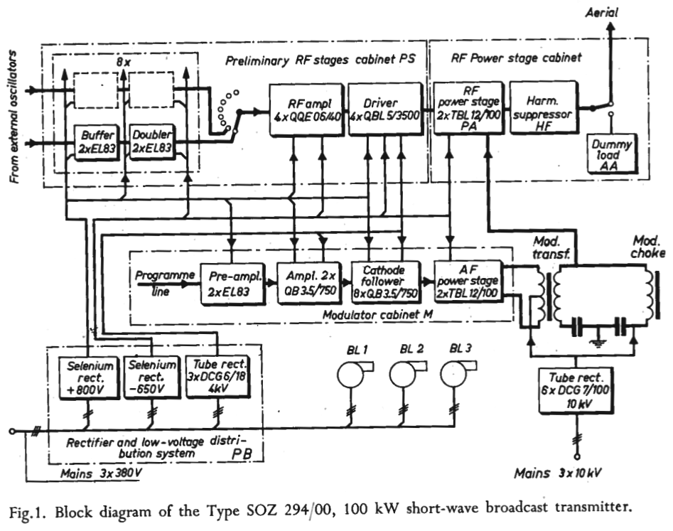
 General arrangement of the transmitter
| carrier frequency | ƒ | = | 26 | Mc/s |
| anode voltage | Va | = | 10.4 | kV |
| grid voltage | Vg | = | -1050 | V |
| anode current | Ia | = | 2 x 6.1 | A |
| grid current | Ig | = | 2 x 1.9 | A |
| anode dissipation | Wia | = | 2 x 12 | kW |
| output on dummy load | Wo | = | 103 | kW |
| efficiency, covering losses in anode circuit and harmonic suppressor |
η |
= |
81 |
% |
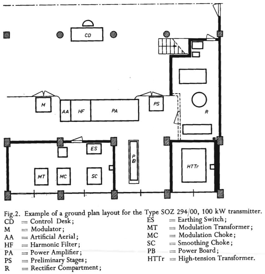
 As shown on the ground plan of Fig. 2, the modulating transformer, the modulating choke and blocking condenser and the anode smoothing filter are placed in a separate high-tension cubicle behind the transmitter. The space to the left of the transmitter is occupied by the anode voltage rectifier equipment. Low-tension distribution equipment and a set of three rectifiers supplying various voltages to the preliminary RF and AF stages are mounted on a common rack which is also placed behind the transmitter front.
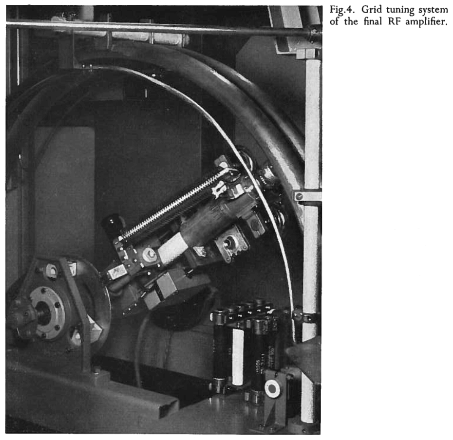
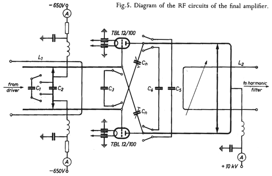 As the frequency increases above 17 Mc/s, the shorting bridge must be brought closer and closer to the grid connections of the tubes. Owing to the increase in frequency and the consequent increase in the current through capacitor C1 the losses in the shorting contacts go up and cause considerable heating. Moreover, the input capacitance of the tubes makes it impossible to attain resonance at the highest frequencies, while satisfactory coupling to the driver stage is also unattainable when the length of the Lecher system becomes too small.
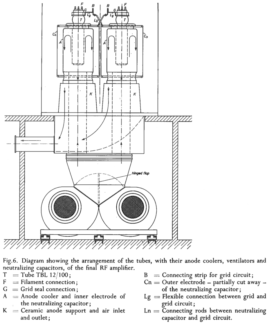 2 Tube arrangement and neutralizing circuits
 In the present transmitter it has been found possible to use a single setting of the neutralizing capacitor over the entire frequency range, a setting which is not critically affected by tube replacements. This has been attained by giving the leads connecting the grid circuit to the grid terminals of the tubes and to the neutralizing capacitors a very definite inductance. The following considerations may make
this clear:
In the present transmitter it has been found possible to use a single setting of the neutralizing capacitor over the entire frequency range, a setting which is not critically affected by tube replacements. This has been attained by giving the leads connecting the grid circuit to the grid terminals of the tubes and to the neutralizing capacitors a very definite inductance. The following considerations may make
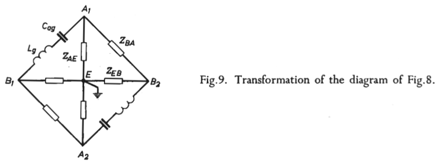
this clear: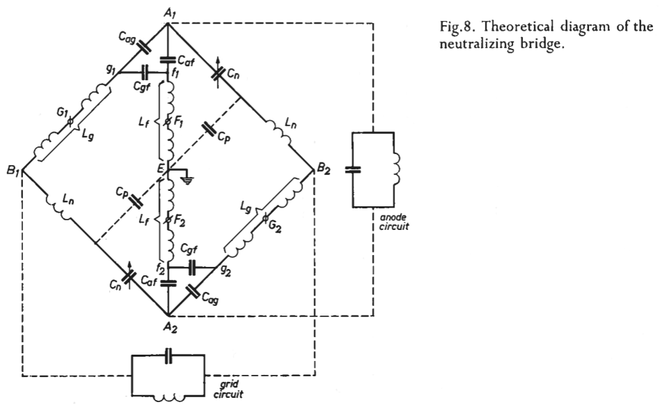 Theoretically, the neutralizing bridge may be represented by the diagram of Fig. 8, in which, among other things, it has been assumed that:
 Combining equations (1) and (2), elements Lg, Ln and Cn can be evaluated. The value of the inductance Ln of the lead from the grid circuit to the outer electrode
of the neutralizing capacitor is found as Ln = Lf Caf/(Cag + Cv).
Combining equations (1) and (2), elements Lg, Ln and Cn can be evaluated. The value of the inductance Ln of the lead from the grid circuit to the outer electrode
of the neutralizing capacitor is found as Ln = Lf Caf/(Cag + Cv).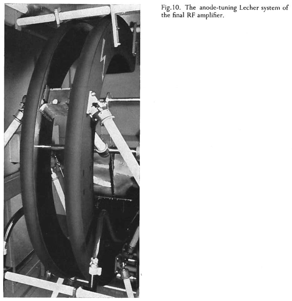 However, the much heavier currents circulating in the anode circuit have made it impossible to use shortening capacitors at the higher frequencies. Under these circumstances the high output capacitance of the transmitter tubes necessitated the choice of a very low characteristic impedance for the anode Lecher system in order to attain resonance at the highest radio frequencies. As a result the lowest frequency to which the Lecher system can be tuned without the parallel connection of capacitors is still comparatively high, viz 12 Mc/s. For lower frequencies capacitors C4 and C5 (see Fig. 5) are connected between the anodes. This is done in two steps which cover the frequency ranges from 12 to 8.5 Mc/s and from 8.5 to 5.9 Mc/s. In view of the low characteristic impedance of the Lecher system fairly high capacities had to be chosen for C4 and C5 and, as a result, the loaded Q of the anode circuit has become comparatively high for a broadcast transmitter of this power; depending on the frequency, it varies approximately between 22 and 45. Such a high loaded Q is an advantage, of course, in that it provides very effective suppression of the radio frequency harmonics generated by the power amplifier, but on the other hand the currents circulating in the anode circuit, which also pass via the shorting contact, become very high. In order to keep the anode circuit losses low the unloaded must therefore also be chosen very high. By a suitable choice of the dimensions for the anode Lecher system, shown in Fig. 10, circuit losses have been kept at a low figure. Depending on the frequency they reach a maximum of 1.5 to 2 kW, which is less than 2% of the carrier power. This volume of heat can easily be carried off by the natural air circulation in the amplifier cabinet.
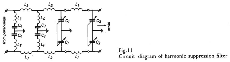 As shown on the diagram of Fig. 11, the harmonic filter proper consists of a single
π-section comprising capacitors C1 and C2, and inductances L1. C1 and C2 are continuously variable vacuum capacitors, driven by a Multiturn Instantuner. The frequency range from 5.9 to 26.1 Mc/s has been divided into four sub-ranges and four sets of coils L 1 have consequently been provided. These are mounted on a turntable rotating on a vertical axis, which is driven by a servomotor and mounted in a separately screened section of the cabinet. Capacitors C1 and C2 are also mounted in separately screened compartments, of which that for C1 also houses the television interference filter. The latter filter comprises four series-resonant circuits composed of capacitors C3 and C4 and inductances L4 and L5, coupled via inductances L3. Inductances L2 serve to couple the television interference filter to the main harmonic suppression filter. The series-resonant circuits are tuned to two frequencies in television band I, for which the interference filter creates a domain of high attenuation.
As shown on the diagram of Fig. 11, the harmonic filter proper consists of a single
π-section comprising capacitors C1 and C2, and inductances L1. C1 and C2 are continuously variable vacuum capacitors, driven by a Multiturn Instantuner. The frequency range from 5.9 to 26.1 Mc/s has been divided into four sub-ranges and four sets of coils L 1 have consequently been provided. These are mounted on a turntable rotating on a vertical axis, which is driven by a servomotor and mounted in a separately screened section of the cabinet. Capacitors C1 and C2 are also mounted in separately screened compartments, of which that for C1 also houses the television interference filter. The latter filter comprises four series-resonant circuits composed of capacitors C3 and C4 and inductances L4 and L5, coupled via inductances L3. Inductances L2 serve to couple the television interference filter to the main harmonic suppression filter. The series-resonant circuits are tuned to two frequencies in television band I, for which the interference filter creates a domain of high attenuation.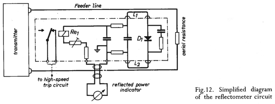 For protection of the harmonic filter against excessive voltages resulting from feeder mismatch, a reflectometer unit has been fitted in the filter cabinet. As the diagram of Fig. 12 shows the reflectometer circuit is coupled capacitively and inductively to the feeder conductors by means of two loops L1 and L2. The inductive voltage vector is 180° out of phase with the capacitive voltage vector.
 Operational details
| TECHNICAL SPECIFICATIONS | |
| Frequency range | 5.95 to 26.1 Mc/s. |
| Carrier power | 100 kW over the entire range. With slight modification the transmitter carrier power can be raised to 120 kW. |
| Audio frequency input level for 100% modulation | Less than 0.775 V across 600 Ω. |
| Linear distortion | Within ± 1 db from 30 to 10,000 c/s at a modulation of 60%. |
| Permissible continuous modulation | 60%. Peak modulation 100%. Short splashes of overmodulation by 6 db can be tolerated. |
| Harmonic distortion |
from 50 to 1000 c/s : < 2%; from 1000 to 3000 c/s : < 2.5%; from 3000 to 10,000 c/s : < 3.5%. |
| Hum and noise level | ≤-60 db, unweighted, referred to 100% modulation. |
| Over-all efficieny, unmodulated | Approx. 55% for 100 kW, and nearly 60% for 120 kW carrier output. |
| Intermodulation distortion | Two signals in the band from 5 to 10 kc/s that differ 180 c/s in frequency and each modulate the transmitter 30%, produce a percentage of intermodulation better than 2% for intermodulation products of the 2nd and 3rd order. |
| TUBE COMPLEMENT | |||||
| RF stages | AF stages and modulator | Rectifiers | |||
| Number | Type | Number | Type | Number | Type |
| 2 | TBL12/100 | 2 | TBL12/100 | 6 | DCG7/100 |
| 4 | QBL5/3500 | 10 | QB3.5/750 | 3 | DCG6/18 |
| 4 | QQE06/40 | 2 | EL83 | ||
| 4 | EL83 | ||||
| THIS TYPE OF TRANSMITTER IS INSTALLED IN THE FOLLOWING COUNTRIES | |||||
| ITU | Country | ITU | Country | ||
| HOL | NETHERLANDS | ||||