| GENERAL DESCRIPTION |
| 50-SW |
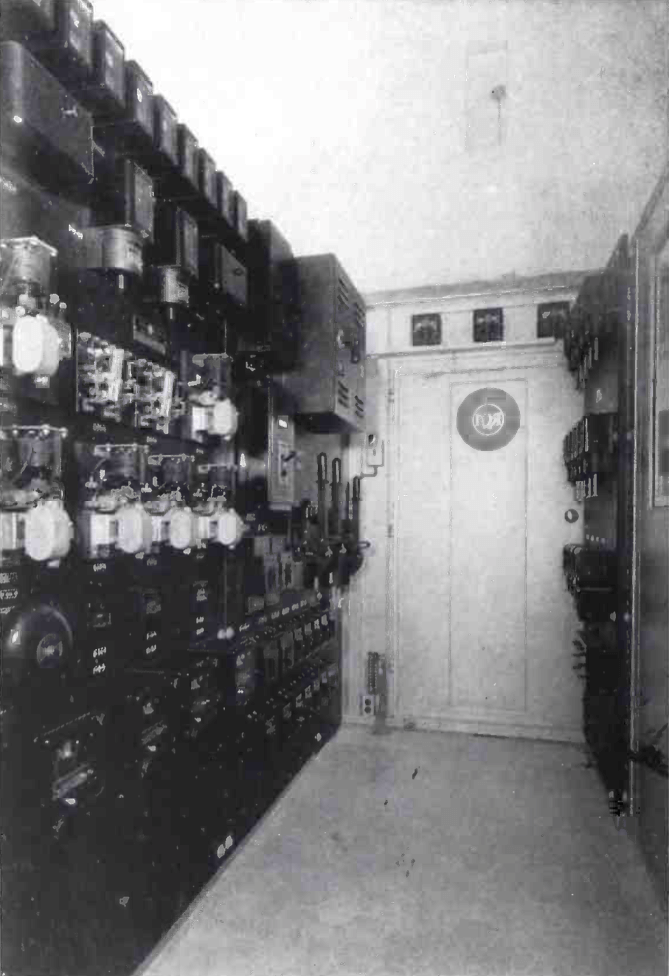 CONTROL CIRCUITS
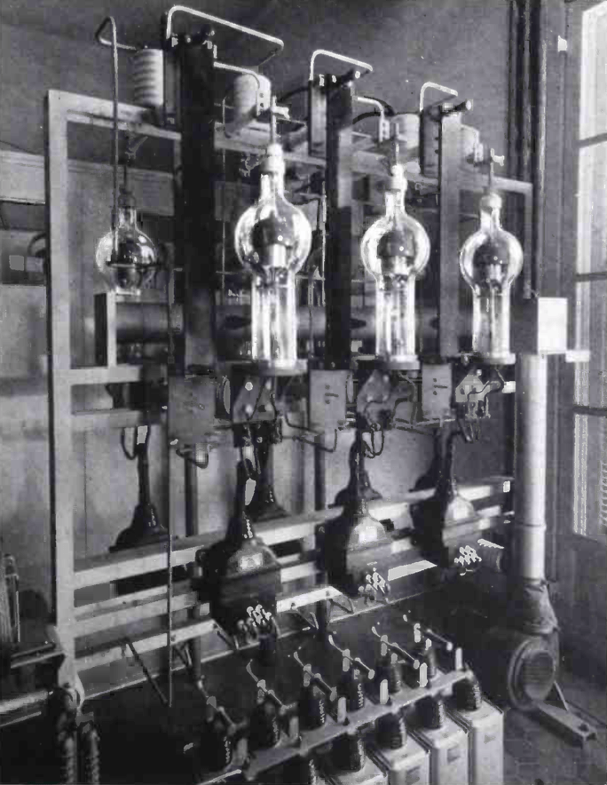 HIGH-VOLTAGE RECTIFIER
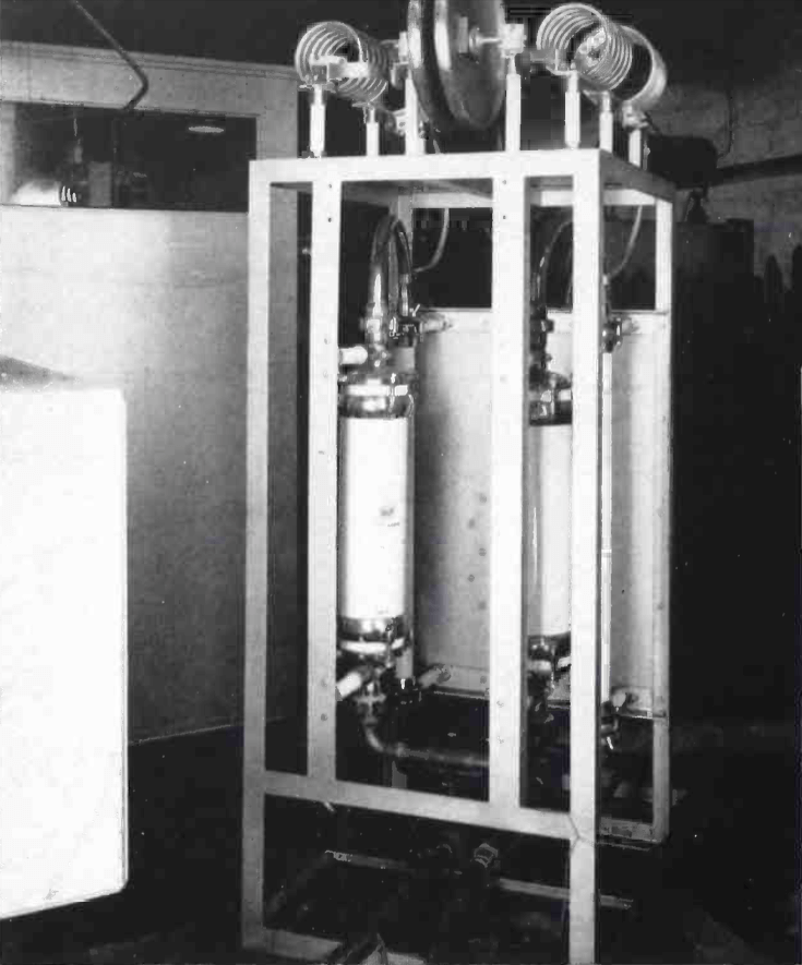 DUMMY ANTENNA
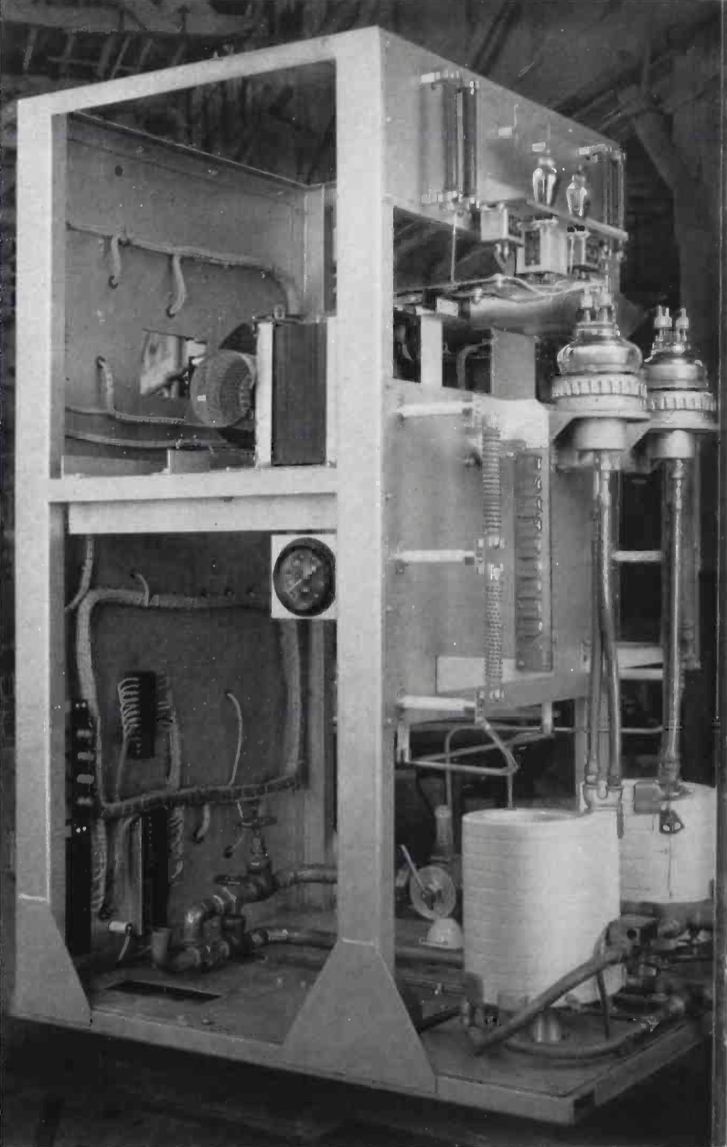 MODULATOR
 EXCITER
 POWER AMPLIFIER
 TANK CIRCUIT
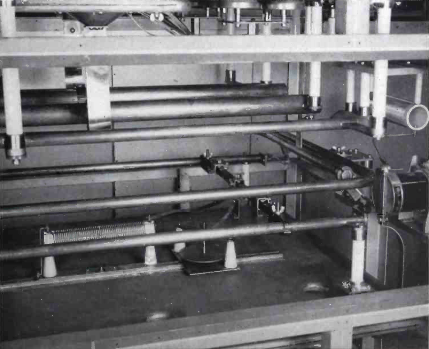 OUTPUT COUPLING
| MI-7330 |
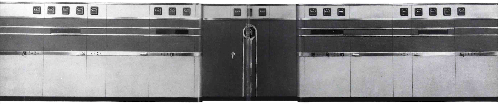
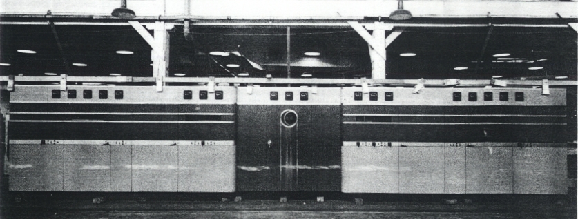 The Short Wave Broadcast Transmitter described herein embodies a number of new developments from the RCA Laboratories which combine to produce an efficient and economical high power equipment for broadcasting in the International Short Wave Bands. Among these developments are new type high-frequency power tubes, simplified automatic control circuits, all a-c operation, new designs of high power audio frequency transformers, and new high~frequency tank circuit designs.
| TECHNICAL SPECIFICATIONS | |
| Type of Emission | A3 - Telephone |
| Power Output (300 to 600 ohm balanced line) | 50 KW |
| Frequency Range | 6 to 22 MC |
| Frequency Stability | 10 parts per million guaranteed |
| Power Supply Requirements | 2300 volts, 50 cycle, 3 phase. Regulation, from no load to full transmitter load, not to exceed 5% of total. Voltage variation due to regulation and other causes should not exceed 10% of nominal 2300 volts. Average program requirements 120 KW - Power Source should be capable of supplying 200 KW. A separate 115 volt, 50 cycle supply for the crystal heaters is required. |
| Power Input: Average program level Modulation Factor = 1 |
Approximately 120 kW Approximately 150 KW |
| Type of Modulation | High level class "B" |
| Audio Frequency Input 600 ohms: Average program level Modulation factor = 1.0 Audio Frequency Response |
0 VU approx. 6 VU Uniform within ±1.5 DB, 30 to 10,000 cycles |
| Audio Frequency Distortion Residual Noise Envelope Distortion |
60 db below 100% modulation 4% r-m-s at 1000 cycles and 90% modulation |
| Specifications may change without notice | |
| TUBE COMPLEMENT | |||||
| RF stages | AF stages and modulator | Rectifiers | |||
| Number | Type | Number | Type | Number | Type |
| 4 | 880 | 2 | 880 | 6 | 857B |
| 4 | 827-R | 8 | 828 | 8 | 872A |
| 4 | 810 | 2 | 1603 | 2 | 836 |
| 4 | 828 | ||||
| 4 | 802 | ||||
| THIS TYPE OF TRANSMITTER IS INSTALLED IN THE FOLLOWING COUNTRIES | |||||
| ITU | Country | ITU | Country | ||
| AUS | AUSTRALIA | B | BRAZIL | ||
| CAN | CANADA | COD | CONGO DEMOCRATIC REPUBLIC | ||
| COG | CONGO REPUBLIC | MRC | MOROCCO | ||
| PAK | PAKISTAN | G | UNITED KINGDOM | ||
| USA | USA | ||||