RCA BHF-100A

GENERAL DESCRIPTION


100 KW SHORTWAVE TRANSMITTER for International Broadcasting

photo RCA BHF-100A In addition to the normal requirements for a good broadcast transmitter such as high fidelity, low operating cost, and easy maintenance, the good shortwave transmitter must possess certain other requisites. Most important among these is that frequency of operation be changed as many as six times a day with a minimum of off-air time. The transmitter must also operate into an antenna, or antenna system, having standing-wave ratios as high as 1.5:1 and impedances from 300 to 600 ohms.
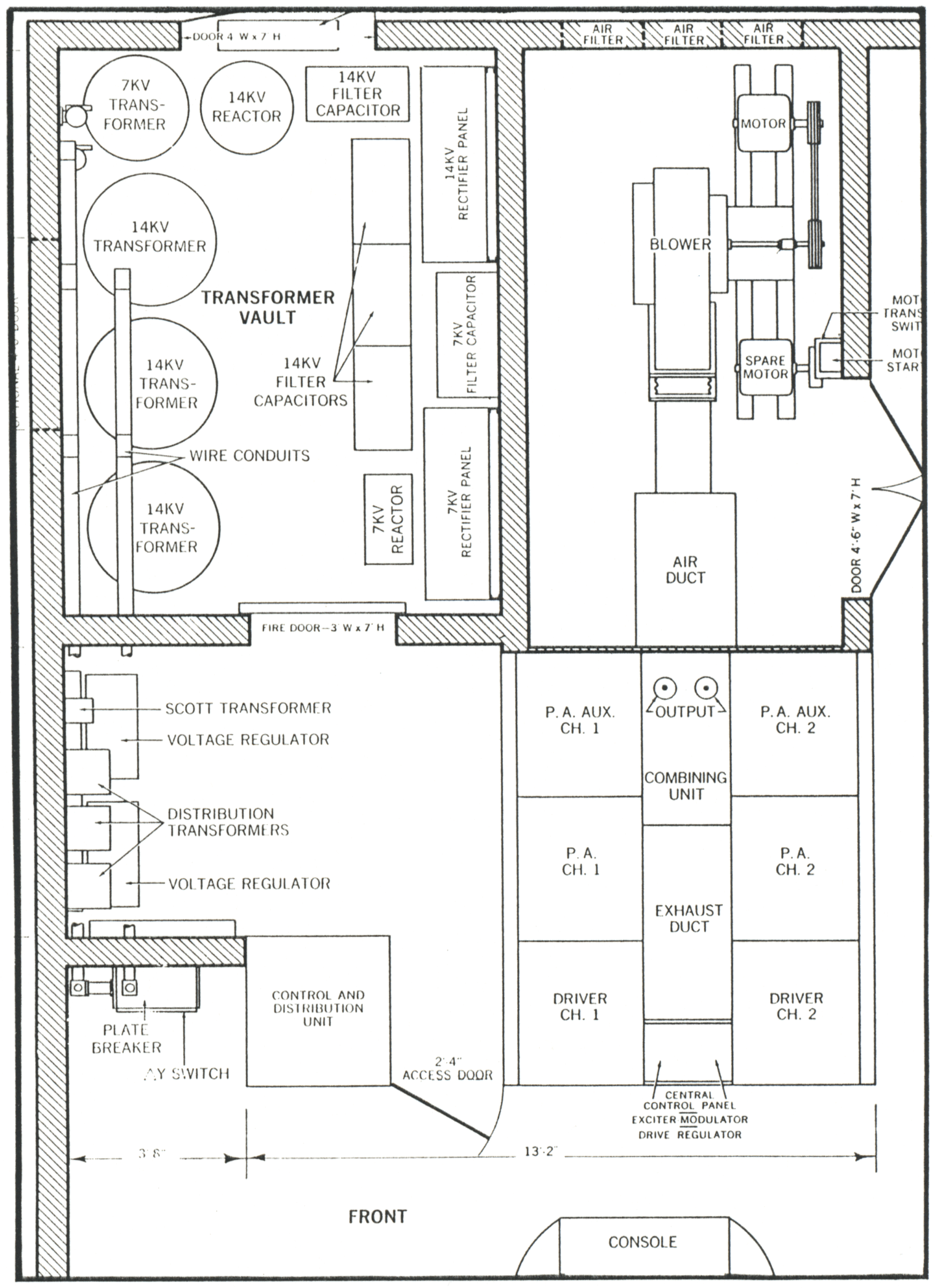
Other requirements, such as high overall efficiency, simple and reliable cooling methods, a minimum of different types of electronic components, lightweight materials, and easy-to-service mechanical components are all dictated by the remote areas where most of these transmitters will be located.

The BHF-l00A shortwave transmitter utilizes the RCA-developed outphasing system of modulation, ampliphase, to achieve excellent performance and meet the stringent requirements imposed on shortwave transmitters. The basic ampliphase system is well-accepted in medium-wave standard broadcast transmitters-over 40 of these, from 10 to 250 kw, are now operating in the field.

The 100 kw BHF-100A occupies significantly less floor space than older 50-kw shortwave trausmitters-a compactness achieved by the ampliphase system.

The heart of the BHF-100A is the exciter-modulator, drive-regulator unit. On each side of this central area, the two RF power-amplifier chains extend toward the rear of the transmitter and are fixed to the "combining-point" balun where the AM, balanced output is produced. The over-all arrangement forms an approximately square transmitter area with complete accessibility to all components in a minimum amount of space.

Amplipliase Modulation

Ampliphase, or outphasing, modulation (originally proposed by H. Chiriex) produces an AM signal by synthesis of two RF signals, each containing linear phase modulation of the intelligence to be transmitted.

Basically, AM is obtained in the transmitter as follows: A single low-level RF source is split into two separate channels having a fixed angle of separation less than 180 degrees. These two sources are then phase-modulated by antiphase audio signals containing the information to be transmitted, amplified in separate channels to the output power level required of the transmitter, and then combined in a common impedance to produce the AM signal.

With two constant and equal current generators of phase difference theta feeding a common resistive load R, the real power PR will be;

PR = (2 I cos (theta/2) )2 R

The load impedances, Z1, and Z2, that the two generators see are:

Z1 = 2 R cos2 (theta/2) + jR sin theta

Z2 = 2 R cos2 (theta/2) - jR sin theta

This, in effect, means that unless compensation of the circuit is made, the generators will be feeding complex loads. Since the generators in question are high-power vacuum tubes in the BHF-100A transmitter, there must be compensation of the circuitry in order to procure maximum efficiency of tube operation.

The practical circuit to get AM from two differentially phase-modulated, high power sources. The plate tank circuit of tube V1, consists of a 90 degree network C1, L1, and 1/2 C3. The plate tank circuit of tube V2 consists of a 90 degree network C2, L2, and 1/2 C3. The 90 degree networks provide:

  1. correct impedance transformation between load and each tube;

  2. a high-Q tank circuit for proper operation of a Class C high-efficiency amplifier; and

  3. a constant-current output source when a constant voltage is supplied to the input.

Capacitors C1 and C2 are also used to compensate for the reactive component of the load seen by each tube. An increase in capacitance on one side and a decrease on the other allows each tube to look at a unity power-factor load and achieve maximum efficiency at one particular phase angle between the two signals. In this particular transmitter, the compensation offset is done at a phase angle theta of 135 degrees, the angle at which carrier level is achieved. Deviations from 135 degrees to produce modulation detunes each tank circuit slightly; however, the power factor does not vary too widely even at 100 per cent modulation, as evidenced by a minor loss in power amplifier efficiency (80 per cent at carrier and 77 per cent at 100 per cent modulation).

Ampliphase Features

Ampliphase modulation is particularly suitable for high-power transmitters. Lower fabrication cost and economy in operation and in utilization of tubes and components are the prinicpal advantages. in the BHF-100A power-amplifier stage, two air-cooled tubes are used in each channel to supply an equal amount of power to the load. Each tube has the same dissipation requirement and the same RF plate swing, never exceeding the swing at carrier level.

In addition to balanced tube operation, there is a balance in plate-circuit configuration. All like elements of the final tank circuit are of equal value, except for the input capacitor to the network. The same equality of the two RF amplifiers is carried through the transmitter to the input stage where the original unmodulated signal is divided.

From the users' standpoint, identical channels mean fewer different spare parts and tubes to be carried in inventory, and the convenient checking of suspect components by side-by-side interchange between channels. Other features are the compact size (no large modulation transformers and reactors are required), the ease with which a complete new modulator can be installed or switched in, and high over-all transmitter efficiency.

Another important feature of the BHF-100A is its capability for fast frequency change . . . a basic requirement for all short-wave broadcast transmitters. The BHF-100A includes a built-in reflectometer and two built-in oscilloscopes for use in frequency change.

The reflectometer accurately measures antenna load, and one of the two CRO's aids in final amplifier tuning (using power factor instead of resonance). The second CRO indicates proper carrier phase-angle.

Furthermore, the BHF-100A changes frequency without use of plug-in coils. This, of course, reduces frequency-change-over time significantly ... often measured in seconds instead of minutes.

Circuit Description

A circuit description of one phase-modulated channel readily applies to the other. This should be so visualized in discussing the circuitry. The RF excitation of approximately 5 watts at any frequency between 1.0 and 9.0 mc is supplied to a broadband transformer at the input to the transmitter. Output of this transformer is push-pull, with a grounded center providing two RF voltages of 180 degrees phase relationship for the two transmitter channels. These 180 degree voltages are then fed to two 600-ohm variable delay lines ganged to one control; rotation of this control delays one signal and advances the other until 135 degree phase separation is achieved.

Output of the delay line is fed to a modified Belaskis Phase Modulator having the triode section of a 6EA8 as the modulator and the pentode section as a tripler to achieve sufficient linear phase modulation in one tube. The Belaskis phase modulator does not require tuning and is most compatible with short-wave requirements in that respect. It is however, difficult to cascade this type of modulator-thus, the 6EA8 tripler requirement.

The output of the tripler, a phase-modulated signal at the transmitter operating frequency, is fed to a high-gain RF amplifier. A 12BV7 tube is used as a limiter to remove incidental AM and 1/3-carrier-frequency modulation front the signal. 'I'he output of the 12BV7 is then fed to the final amplifier of the exciter modulator, a Class C power amplifier having approximately a 7-watt output at 75-ohm impedance.

It is interesting that the full range of 3 to 27 mc is covered in four bands. A frequency change can be made by moving one band selector switch to the proper position and adjusting only one control, which drives six inductor tuning slugs to a calibrated point. This rapid phase-modulator tuning is of sufficient accuracy to permit the transmitter to be set up and opeerated without utilizing the fine trimmers of each circuit. The fine-tuning controls provided can, however, be adjusted while programming to optimize performance.

The exciter-modulator output is fed through a 75-ohm cable to a broadband transformer driving the intermediate power amplifier-a straightforward Class C amplifier utilizing a parallel pair of 7094 tetrodes to provide approximately 100 watts to the driver stage. Although the input circuitry to this stage is very broad it is necessary to compensate the circuit by switching four shunt indicators to cover the band.

The intermediate power amplifier output is tuned by a variable coil in parallel with a capacity divider formed by blocking condensers and the input capacitance of the driver tubes. The two driver tubes are grid-modulated amplifiers, providing proper drive for the final stage under all modulation conditions. Because of the widely varying drive requirements and load impedances, the two tubes of this stage are biased at different levels. Thus, at carrier and below, one tube is supplying power; above carrier level, both tubes are supplying power to drive the final stage. To match the low input impedance of the grounded-grid power amplifier to the relatively high impedance of the driver stage, a 180 degree network plate-tank circuit is used. This network meets the special requirements of feeding a load of a varying nature. Load impedance at the peak of modulation is low and at the trough of modulation is high. The network accomplishes the correct transformation ratios and precludes incidental phase modulation (usually resulting from variable loads). There are other satisfactory methods, such as transformer coupling; however, in the BHF-100A the 180 degree network provides greater tuning simplicity.

Each final power amplifier utilizes two ML-6697 air-cooled triodes in a grounded grid configuration to produce 50 kw of carrier power and 200 kw of peak modulation power. The input of this stage consists of the output portion of the special 180 degree network with its output capacitance located directly between the two tubes. In addition to this capacitance, a shunt inductance is required at the high frequency end of the spectrum to compensate for the high input capacitance of the tubes. This shunt inductance is also one arm of a neutralizing bridge which prevents incidental phase modulation.

A 90 degree network transforms the final output circuit from a constant-voltage source to a constant-current source, it is then combined in the common load with current from the other channel amplifier to produce AM. The combined output is fed through a section of the line containing a reflectometer to the balun for transformation from a single-ended 15-ohm output to a balanced output of 300 ohms. Electrically, the balun consists of a series-tuned resonant-primary circuit inductively coupled to a balanced parallel-resonant secondary circuit. In addition to serving as an impedance matching device, the balun also provides RF harmonic attenuation.

The remaining components of the transmitter such as power supplies, control circuits, protective devices and metering circuits are conventional and compatible with the high design criteria used throughout.

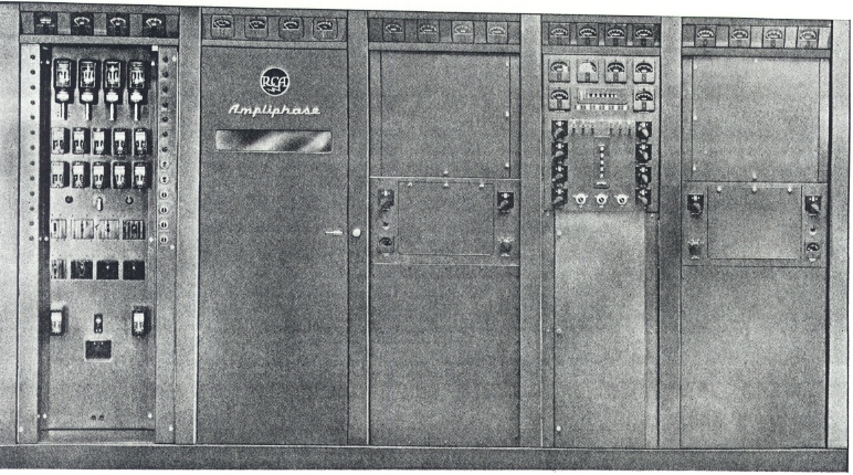
Special Electrical-Mechanical Component Design
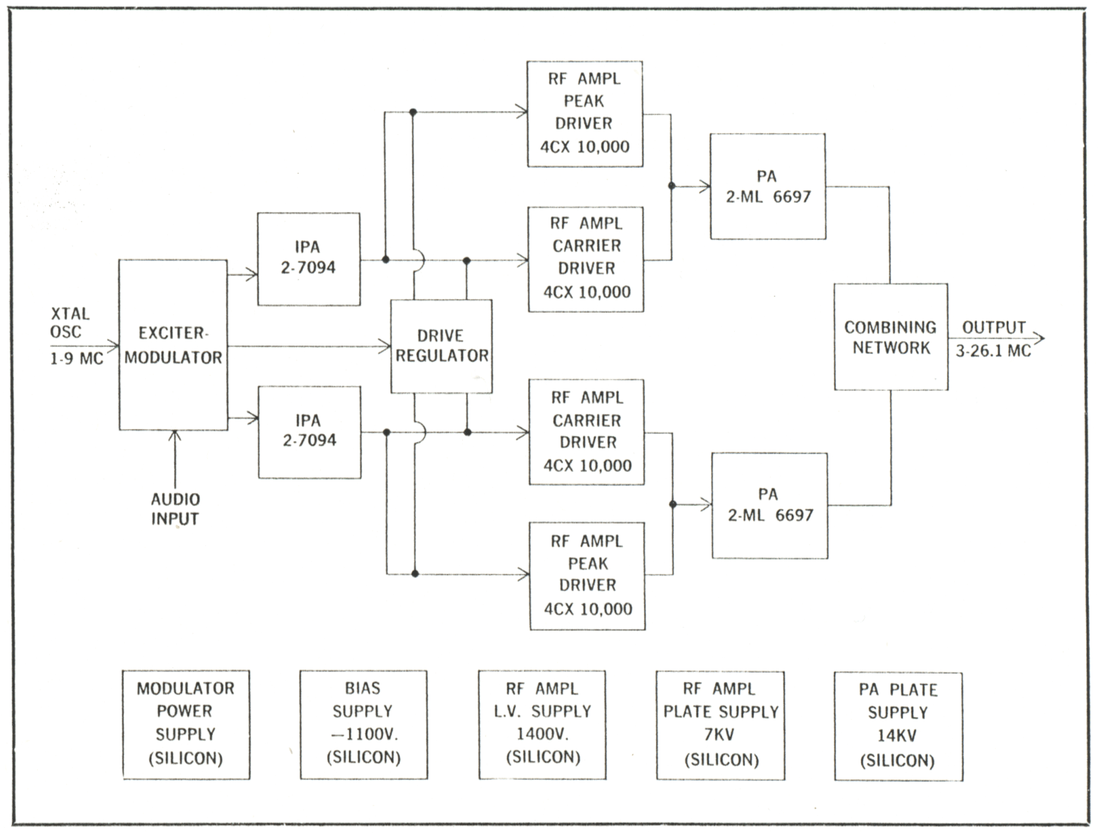
Because of the wide frequency range of the transmitter and the high power level involved, many of the electrical components had to be designed and fabricated rather than purchased. Close cooperation between electrical and mechanical design engineers resulted in the use of new materials and ideas that have given good electrical performance and minimum product cost.

A major problem area in high-power transmitter design is to provide an economical trouble-free variable inductor. The approach used in the power amplifier and the balun of the BHF-100A has proven highly successful under actual operation. Basically, the line inductor consists of two sets of parallel 11/2-inch-diameter hard copper tubing, ranging in separation from 10 to 12 inches; the adjustable (sliding) shorting bar is made from 11/2-inch-square hard-brass tubing of 0.060-inch wall thickness. By notching and slotting the contact area of the square tubing, fingers are shaped to provide good line contact along the entire path of travel. These fingers tend to have a leaf-spring action, creating a direct positive pressure on the copper line and reducing the possibility of joint-heating and resultant failure. With this configuration, five mechanical joints of the rotary-type inductor are reduced to two. Contacts are mounted in pairs on a melamine crossbar which is driven by a pair of chain-connected lead screws.

In addition to these contacts, a series-parallel switching arrangement in the lines allows a greater range of inductance. With this, the operator may change the set of four 11/2-inch lines arranged on the corners of a 10- by 12-inch rectangle from series to parallel configuration. The mechanism is operated by a motor drive interlocked by limit switches and an overriding slip clutch.

The balun is situated between the two RF cabinets in an area 22 by 40 inches. This system consists of three lines. The center one serves as a primary coil, and the two outer lines, either in series or parallel, serve as the secondary coil. Since the primary coil is completely surrounded by an electrostatic shield and shunt capacitance to ground is high, it is necessary to "trombone" this line. By linking drives of the three movable shorts to a pair of lead screws inside the primary lines, the bottom of the primary line is allowed to slide over its upper portion. Thus, at the high-frequency end of the band, the volume of the coil is half that of the low end.

Since the only way to drive this collapsing line and derive maximum capacitance reduction is by having lead screws operating directly on the line, an insulating material with the correct properties had to be found. The lead-screw material chosen was polypropylene, which has electrical properties very similar to teflon, mechanical properties similar to nylon, and a cost about a third that of teflon.

Several other mechanical features were incorporated into the RF units. In mounting the power-amplifier tubes (ML-6697) in each channel, a Rexolite shelf was used as the tube support. The mechanical strength of Rexolite (a crossed-linked styrene co-polymer) is sufficient to support the 82-pound weight of the tubes. Rexolite has many other advantages in this application including its low dielectric-constant, low loss-factor and relatively high imperveance to tracking.

As is usual in most transmitters, the cooling problem in the BHF-100A proved to be the power-amplifier tube anode glass-metal seal. The solution was to notch the plenum portion of the ML-6697 air distributor at its point of contact with the cooling fins of the tube. Thus, sufficient cooling air is channeled over the seal surface. The area between the two RF channels and the front of the combining network forms an air exhaust duct for the driver and power-amplifier tubes and houses the various tuning drives which terminate at the central control panel.

Central Control Panel

From the standpoint of the transmitter operator, the most important area of the transmitter is the central control panel. The upper portion of the panel is devoted to the final-tube current meters and the read out indicators of the motor driven inductors. Directly above the indicators is a roll chart containing tuning data for six precalibrated frequencies. Directly below the indicators are the motor operating switches for the inductor driving motors. Along either side of this panel are all the variable-capacitor tuning controls with their roll chart located directly in the center.

On either side of the vertical roll chart is a plate-to-cathode monitoring oscilloscope which indicates unity power factor or maximum efficiency of the final-amplifier tubes, and also the phase and loading status of the double-pi network driving the final amplifiers. These oscilloscopes are direct-reading and so designed and constructed that front 3.0 to 26.0 mc there is less than 3 degrees differential between the vertical and horizontal deflection circuits.

The deflection circuits also contain low pass filter networks so that the straightline fundamental indication on the scope will not be misread because of harmonic distortion.

Transmitter Performance

Seven of the type BHF-100A transmitters have been shipped to the international market and an eighth is presently set up in Camden for further testing and demonstration.

The application of the ampliphase concept to short-wave transmitters permits short-wave broadcasters the advantages that medium-wave broadcasters, using ampliphase transmitters, enjoy. Among these are: reduced floor-space requirements, greater efficiency, lower operating costs. Also, elimination of costly and bulky iron-core modulation transformers, superb audio at high modulation levels, and (often an important consideration) power increase without equipment obsolescence. As a matter of fact, equipment is now in manufacture for the diplexing of two 100-kw Ampliphase transmitters to provide 200 kw of power from a single r-f frequency source.

TUBE COMPLEMENT
RF stages AF stages and modulator Rectifiers
Number Type Number Type Number Type
4 ML 6697


4 4CX10000


4 7094


THIS TYPE OF TRANSMITTER IS INSTALLED IN THE FOLLOWING COUNTRIES

ITU Country
ITU Country