RCA BHF-100B

GENERAL DESCRIPTION


BHF-100B High Frequency Broadcast Transmitter

photo RCA BHF-100B GENERAL

The RCA Type BHF-100B 100 KW Shortwave Transmitter is designed for high-fidelity radio-telephone transmission in the International Broadcast bands. Continuous coverage of the frequency range from 93.7 meters (3.2 megacycles) to 11.5 meters (26.1 megacycles) is provided through band-switching. The transmitter employs a high-efficiency type of phase-to-amplitude modulation.

All r-f and modulation components are housed in four equipment cabinets and an exciter / modulator assembly. Except for a cabinet located in a rear area. Floor area requirements for transmitter installation have been kept to a minimum while providing adequate work space and free access to components. The entire transmitter, complete with input equipment and an accessory control console, can be housed easily in a building 6.7 meters (22 feet) by 9.1 meters (30 feet).

The BHF-l00B has many built-in reliability and protective features.

Ample cooling is provided for all r-f and modulation components by a 244-cubic meter per minute forced-air system supplied by a single blower external to the equipment cabinets.

All necessary power distribution and switchgear equipment from the point at which the 380/460-volt, three-phase power enters the system is supplied as part of the transmitter. Full d-c and a-c overload protection is provided throughout. Door and panel interlocks are used extensively to protect operating personnel.

For reliability, all power supplies use silicon rectifiers operating well below their maximum ratings.

Designed for use with or without a control console, the transmitter may be controlled remotely by the addition of the BTC-1B Control Console Equipment listed in the EQUIPMENT LIST. Provisions have been made in the transmitter wiring for remote control operation.

photo RCA BHF-100B CONSTRUCTION

The cabinets which house the transmitter r-f, modulation, and control components are aluminum; the cabines bases are steel. All components in the cabinets are accessible for maintenance and servicing through full-length doors or through panels secured to the cabinets with quick-release fasteners. Wiring interconnections among these units are made by individual cable runs through a special duct installed on top of the cabinets. The power-distribution equipment is floor- and wall-mounted. All high-voltage a-c and d-c cable runs are made through conduit or wall-mounted square ducts. The location of the major components or associated group of components in the transmitter cabinets is shown in figure 2. All doors and panels that provide access to areas containing high voltage are interlocked. Any of these interlocks will remove high voltage and also will automatically ground the high-voltage d-c output circuits. Convenience outlets for 110-volt a-c power are installed in the control and distribution unit and the rack-panel assembly housing the exciter/modulator, drive regulator, and power supply unit for use with 110-volt test equipment. An external stepdown transformer must be supplied, if 220-volt building service is all that is available. Compartment lights are provided in the control and distribution unit for ease of operation and maintenance of the control components.

FUNCTIONAL DESCRIPTION

The circuits of the BHF-100B are shown functionally in the block diagram. R-f excitation of approximately 5 watts at any frequency between 1.1 and 8.7 megacycles is supplied from an external sourct to the input transformer of the transmiter. The output from this transformer is push-pull, with a grounded center tap providing two r-f voltages 180° out of phase. These voltages are applied to two ganged, variable delay lines. The delay lines are adjusted so that the phase separation between the two applied voltages is reduced to about 163° at the outputs of the delay lines. These two voltages are then applied to phase modulators of two separate but electrically identical r-f channels. The r-f voltages are processed identically through these channels while the phase separation is maintained at about 130° (after frequency and phase tripling).

The audio input to the transmitter is applied through a modulation level control to a transformer with split secondary, providing two audio volatages 180° out of phase. These voltages are amplified by separate audio amplifiers, each of which feeds one of the phase modulators of the separate r-f channels. In order to prevent possible overmodulation, the phase modulator audio signal passes through a clipper circuit. The resultant phase-modulated signal from the phase modulator stage is applied to a frequency tripler. This stage raises the frequency of the phase-modulated signal to the desired transmitter operating frequency. The phase-modulated signal, at the transmitter operating frequency, is fed to a high-gain r-f amplifier chich also provides limiting to remove incidental AM and 1/3-carrier-frequency modulation from the signal. The final stages of the exciter/modulator are Class C power amplifiers; each provides approximately 10 watts of drive to the intermediate power amplifiers of their respective r-f channels. Bandswitching is employed in the exciter/modulator to cover the 3.2- to 26.1-megacycle operating range of the transmitter in four bands.

photo RCA BHF-100B The IPA's are Class C amplifier. employing a parallel pair of 7094 tetrodes to provide approximately 100 watts to the following driver stage. Input and output circuits of the IPA's are frequency compensated by bandswitched inductive elements. Proper drive for the final power amplifier stage of each channel is provided by a driver stage consisting of two 4CX10,000 tubes. Because of the widely varying drive requirements and load impedances, the two driver tubes are biased at different levels. Thus, at the carrier power level and below, one tube (carrier driver) is supplying power; above the carrier power level, both tubes (carrier and peak driver) are supplying power to drive the final stage. A 180° network (two 90° pi networks in cascade) is used to match the relatively high impedance of the driver stage to the low input impedance of the grounded-grid power amplifiers which follow. This network provides the correct transformation ratios under varying load impedances without incidental phase modulation.
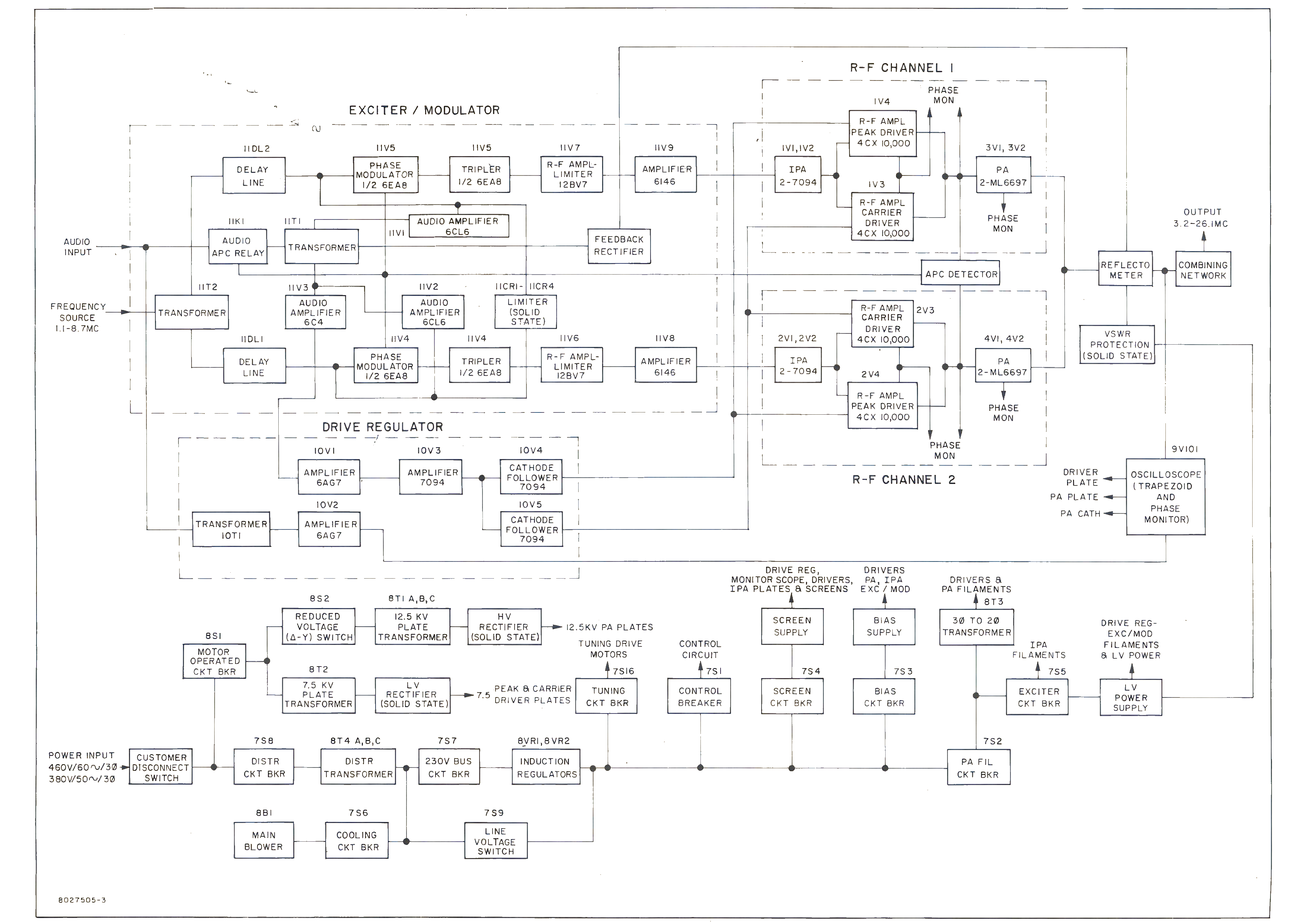
Each final power amplifier uses two 6697 air-cooled triodes in a grounded-grid configuration to produce 50 kw of carrier power and 200 kw of peak modulatino power. A 90° pi network transforms the final output circuit from a constant-voltage source to a constant-current source. Current from the PA's of both r-f channels is combined in a common load to produce the desired AM signal from the two phase-modulated inputs. The amplitude-modulated r-f output is fed through a section of transmission line containing a reflectometer to a combining network. The combining network is a balun which transforms a single-ended 15-ohm output to a balanced output of approximately 300 ohms.

The audio input to the transmitter, in addition to its use in phase modulation, is amplified and applied to a drive regulator circuit consisting of audio amplifiers driving a pair of cathode followers. The outputs from the cathode followers are applied to the grids of the drivers. The drive regulator, functioning in synchronism with the phase-modulation process, provides a dynamic bias variation at the control grids of the drivers. Grid modulation of the driver stage provides a varying r-f drive level to the power amplifiers in direct relationship to the load they experience at all percentages of modulation. Consequently, maximum PA plate efficiency is maintained over the complete audio cycle.

A portion of the output signal is taken from the 15-ohm line section, rectified (demodulated), and applied as degenerative feedback to the audio amplifiers driving the modulators in the exciter/modulator. This reduces noise and distortion to improve the fidelity of the transmitter signal.

A sample of the VSWR signal is also coupled from the 15-ohm line section, rectified, and applied to the VSWR protection circuits. The protection circuits are arranged so that a temporary VSWR fault condition will cut off the r-f drive and modulation by disabling the +250 vdc exciter/modulator power supply, allow the fault to clear, and then automatically return r-f drive and modulation to resume normal operation. An isolated fault of this nature will not disable the plate supplies but it will seal in a carrier-off indicator to record the occurrence. Should the fault persist, the control circuitry removes plate power if serveral attempts to recover normal operation are unsuccessful.

The 380/460-volt a-c distribution system and the d-c supply components shown are conventional and are compatible with the high design criteria used throughout.

photo RCA BHF-100B

TUBE COMPLEMENT
RF stages AF stages and modulator Rectifiers
Number Type Number Type Number Type
4 ML-6697


4 4CX10,000


4 7094


THIS TYPE OF TRANSMITTER IS INSTALLED IN THE FOLLOWING COUNTRIES

ITU Country
ITU Country
flag EQA EQA ECUADOR flag PAK PAK PAKISTAN
flag PLW PLW PALAU flag USA USA USA
flag CVA CVA VATICAN CITY