| GENERAL DESCRIPTION |
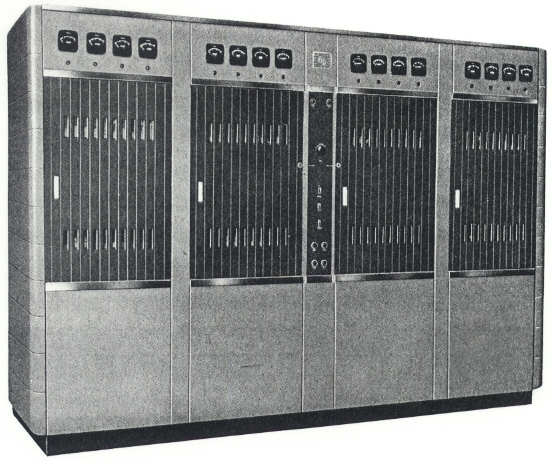 FEATURES
| TECHNICAL SPECIFICATIONS | |
| Type of Emission | A 3 |
| Output Frequency Range | 3.2 to 26.1 mcs |
| Power Output at Transmitter terminals | 10 kw unmodulated |
| Output Load Impedance | 350 to 650 ohms resistive ±JO.1R |
| Radio Frequency Harmonic Output | Less than 200 milliwatts |
| Frequency Stability | 0.003% |
| Type of Modulation | High level, Class B |
| Program Input Impedance | 150 or 600 ohms |
| Program Input Level (100% Modulation) | +10 dbm ±2 db |
| Audio Frequency Response | ±1.0 db 50 to 7,500 cycles ±2.0 db 30 to 10,000 cycles |
| Audio Frequency Distortion (at 95% Modulation, 50 to 5,000 cycles) | 4.0% RMS maximum |
| Noise Level, Unweighted (below 100% Modulation) | 54 db |
| Carrier Regulation | Less than 5% up to 100% modulation |
| Power Consumption Without Modulation 40% Modulation 100% Modulation |
22 kw approx. 28 kw approx. 35 kw approx. |
| Power Factor | .85 |
| Power Line Requirements | 230 volts, 3 phase, 3 wire, 50 cycles |
| Permissible Power Line Regulation | 5% zero to full load |
| Permissible Power Line Combined Regulation and Variation Limits | ±5% |
| Ambient Temperature | +45 degrees C max. |
| Elevation | 8000 feet max. |
| Frequency Change Time (a) 4 to 22 Megacycle Range (b) Range (a) to 26.1 or 3.2 Megacycle Ranges |
120 seconds max. 300 seconds max. |
| Specifications may change without notice | |
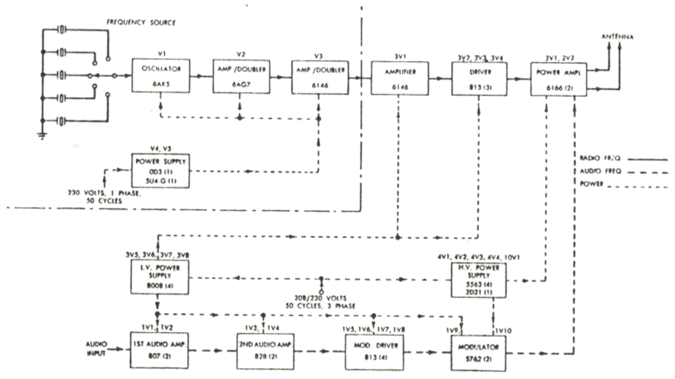
| TUBE COMPLEMENT | |||||
| RF stages | AF stages and modulator | Rectifiers | |||
| Number | Type | Number | Type | Number | Type |
| 2 | 6166 | 2 | 5762 | 4 | 5563 |
| 3 | 813 | 4 | 813 | 4 | 8008 |
| 1 | 6146 | 2 | 828 | 1 | 2D21 |
| 2 | 807 | ||||
| THIS TYPE OF TRANSMITTER IS INSTALLED IN THE FOLLOWING COUNTRIES | |||||
| ITU | Country | ITU | Country | ||