| GENERAL DESCRIPTION |
 FEATURES
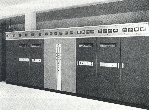
 Control Console
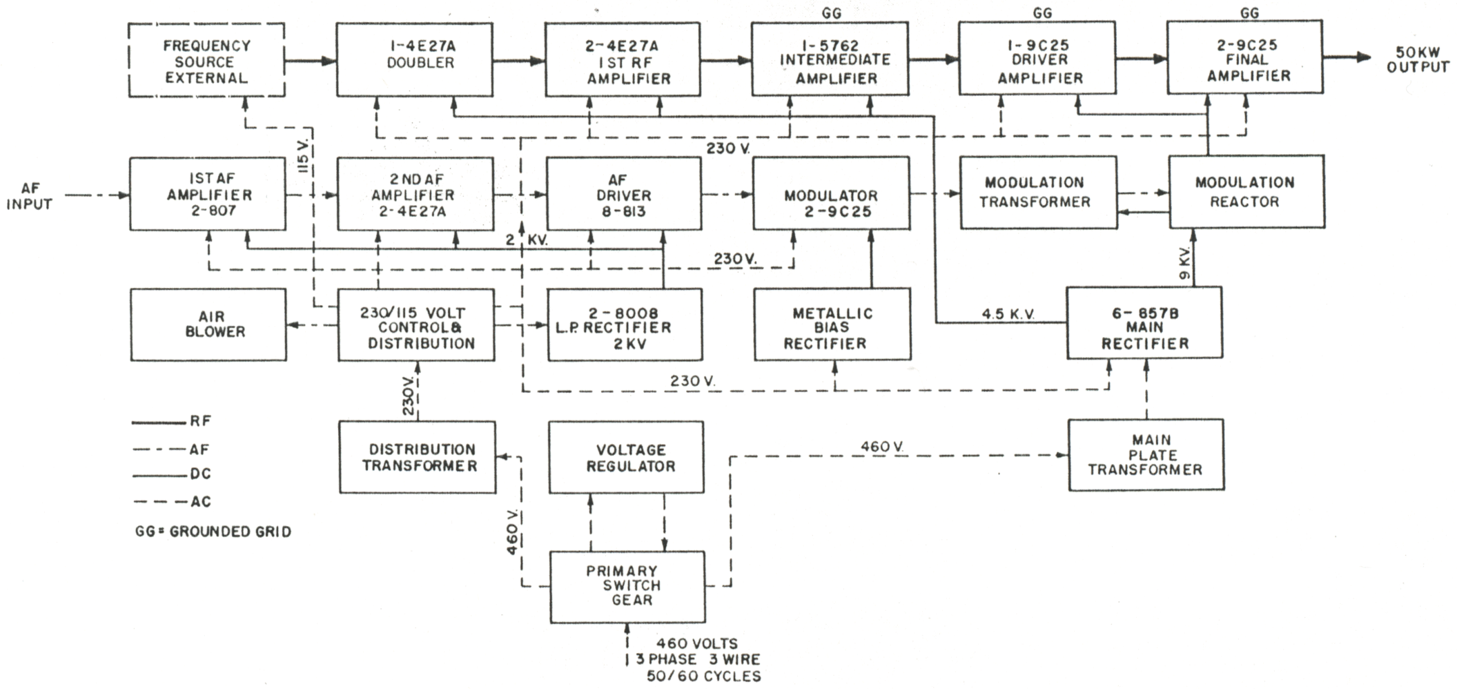
| TECHNICAL SPECIFICATIONS | |
| Type of Emission | A 3 (telephone) |
| Output Frequency Range | Any frequency within the ranges 3.9 to 22.0 mc; and 25.6 to 26.1 mc |
| Stability | Determined by frequency source |
| RF Power Required from External Frequency Source | 2 watts minimum |
| Power Output | Not less than 50 kw for frequency range of 3.9 to 22.0 mc Not less than 40 kw for frequency range of 25.6 to 26.1 mc |
| Modulation | High level Class B |
| Capability 400 Cycles 50 to 7500 Cycles |
Not less than 100 per cent Not less than 90 per cent |
| Audio Frequency Response | ±2 db 30 to 10,000 cycles (Input reference level corresponding to 60 per cent modulation at 1000 cycles) |
| Residual Modulation (100% Modulation) | 56 db below 100 per cent modulation |
| Envelope Distortion | Less than 4.0 per cent rms (with 90 per cent modulation at 1000 cycles) |
| Input Impedance | 600 ohms |
| Input Level Required for Full Modulation (400 cycles) | +10 ±2 dbm |
| R-F Output Load Impedance | 300 to 600 ohms resistive |
| Power Sources For Main Supply For Auxiliary Supply |
460 volts, 50 cycles, 3 phase, 3 wire. Allowable regulation 5.0 per cent. Allowable total voltage variation including regulation, 46 volts. 115 volt, 50 cycle, single phase, approximately 500 watts |
| Power Consumption (less Auxiliaries) 0% Modulation 30% Modulation 100% Modulation |
110 kw 125 kw 165 kw |
| Power Factor (at 100% Modulation) | At least 90 per cent |
| Specifications may change without notice | |
| TUBE COMPLEMENT | |||||
| RF stages | AF stages and modulator | Rectifiers | |||
| Number | Type | Number | Type | Number | Type |
| 3 | 9C25 | 2 | 9C25 | 6 | 857B |
| 1 | 5762 | 8 | 813 | 2 | 8008 |
| 3 | 5-125B / 4E27A | 2 | 5-125B / 4E27A | ||
| 2 | 807 | ||||
| THIS TYPE OF TRANSMITTER IS INSTALLED IN THE FOLLOWING COUNTRIES | |||||
| ITU | Country | ITU | Country | ||
| AUS | AUSTRALIA | CLM | COLOMBIA | ||
| POR | PORTUGAL | ||||