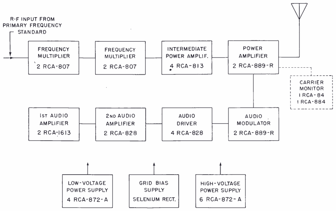
RCA ET-7285

GENERAL DESCRIPTION


photo RCA ET-7285

...WWV...WWV...WWV... - Broadcasting Frequency Standards with RCA Type ET-7285 Transmitters

Covering the United States and reaching into the far corners of the world, the standard frequency and time interval services of the National Bureau of Standards are providing both audio and radio-frequency standards which have an accuracy, as transmitted, that is better than one part in 10,000,000. Under the direction of Dr. J. H. Dellinger, head of the Bureau's Radio Section, Radio Station WWV, Washington, D. C., is operated to furnish this standard frequency broadcast service. WWV passed the one-year mark this summer in its new home which is completely equipped with new and expanded facilities. Directly charged with planning, engineering and operation of this station is Mr. W. D. George and his assistants, Messrs. G. H. Lester and M. C. Selby.

The transmitter building, shown on this page, which was especially designed and built to house the radio transmission activities of the Bureau of Standards, is the home of the WWV transmitting plant. Constructed of brick with a steel frame and poured concrete floor and ceiling, this single story building measures approximately 93 feet long, 43 feet wide and 22 feet high.

This transmitter plant, located at Beltsville, Maryland, is equipped with four RCA Type ET-7285 High-Frequency Broadcast Transmitters. Operating on any one of six carrier frequencies, 2.5 mc., 5.0 mc., 10 mc., 15 mc., 20 mc. or 25 mc., at least three of these transmitters are on the air at all times to maintain the continuous 24-hour schedule. In service over a year and operating for weeks at a stretch, without shutdown, these units have given new proof of the ruggedness and dependability of RCA transmitting equipment.

The ET-7285 Transmitters were originally designed for a power output of 7.5 kw. at 20 mc. Subsequent tests and actual operation proved this value was conservative and could be considerably exceeded at all carrier frequencies. These transmitters are now operated by the Bureau at a nominal output of 10 kw.

At least three of these transmitters operating on separate carrier frequencies are on the air at all times to insure reliable coverage. The radio frequencies now in use are:

 2.5 megacycles (2500 kilocycles per second broadcast from 7:00 P.M. to 9:00 A.M. EWT (2300 to 1300 GMT).

 5 megacycles (5000 kilocycles) per second broadcast continuously day and night.

 10 megacycles (10,000 kilocycles per second broadcast continuously day and night.

 15 megacycles (15,000 kilocycles 1 per second broadcast from 7:00 A.M. to 7:00 P.M. EWT (1100 to 2300 GMT).

The lowest frequency provides service to short distances, and the highest to great distances.

Two standard audio frequencies are used to modulate the r-f carriers. Both 440 and 4000 cycles per second are broadcast continuously on 10 and 15 megacycles. Both are also on the 5 megacycle carrier in the day time, but only 440 is used from 7:00 P.M. to 7:00 A.M. EWT. Only the 440 signal is on the 2.5 megacycle carrier.

The 440 cycle note is the standard musical pitch, A above middle C; the 4000 cycle note is a useful standard audio-frequency for laboratory measurements. In addition, there is superimposed on all carrier frequencies, a pulse of 0.005 seconds duration which occurs periodically at intervals of precisely one second. The pulse consists of five cycles, each of 0.001 second duration, and is heard as a faint tick when listening to the broadcast; it provides a useful standard of time interval, for purposes of physical measurements, and may be used as an accurate time signal.

A unique feature of these transmitters is the fact that they possess no oscillator. A primary frequency standard located in a vault 20 feet underground supplies one watt of r-f energy at 2500 kilocycles per second to the 1st amplifier of each transmitter. This 2.5 mc. signal is then multipled by two harmonic generators to produce the desired carrier frequency.

Such features as automatic starting and stopping of the transmitters in accordance with a preset schedule and dual operation of two equipments wherein the failure of modulation or carrier of the transmitter in operation will automatically shut it down and start up a stand -by unit, play a vital part in the maintenance of the rigid broadcast schedule.

A large share of credit is due to the engineers who operate the transmitters, Mr. G. H. Lester, and his assistants, Messrs. J. M. Shaull and E. C. Wolzien. Their strict maintenance program includes a service period of three days per transmitter during which the entire equipment is gone over with a fine-tooth comb. The fact that WWV can boast a record of a single momentary outage during an operating period of three months, for all transmitters combined, is due not only to the equipment, but also to the station's rigid maintenance policy. A front view of two of the transmitters at WWV is shown below.

Complete isolation of each transmitting equipment within individual partitions provides a pleasing and finished external appearance and, at the same time, maximum safety for the operating personnel. To prevent accidental opening of any of the inter-locked access doors (which would, of course, shut the transmitter down), specially designed electric locks secure these doors when the high voltage switch is closed. A detailed description of the arrangement of these units and of the units themselves will be found on the following pages.

photo RCA ET-7285

photo RCA ET-7285

THE INTERIOR OF STATION WWV

The four RCA transmitters at WWV are installed in the west wing as shown in the photographs on this page. Additional space and facilities are provided for two more equipments to complete an ultimate plant of six transmitting units. By orienting transmitters, as shown in the accompanying views, a minimum of movement is required for the operator to check all four transmitters. Viewing ports in the front and rear enclosures assure complete visibility of all components.

Wire trenches, covered with metal plates (visible in the floor) feed into each transmitter all necessary external connections. The power distribution board at the far end of the room is the connecting link between the substation located outside the building and the individual transmitters. A twenty-pen Esterline-Angus recorder mounted on the left-hand side of this board provides a permanent record of all outages and power failures. The station derives its power from two independent sources. The feeders are tied into the distribution board through the automatic transfer switch contained in the panel mounted on the far wall immediately to the left of the distribution board.

The transmission lines, suspended just below the ceiling, couple the transmitters to any of the twelve antennas which are provided in duplicate for the six carrier frequencies.

photo RCA ET-7285

RCA ET-7285 diagram

THE ET-7285 TRANSMITTERS AT WWV

The arrangement of the ET-7285 Transmitter Equipment is one of functional design wherein the basic circuits for radio-frequency, audio-frequency, and power and control are each contained in an individual cubicle.

The various circuit components in each of these sections are mounted on vertical panels in the "vertical-chassis" style first introduced in RCA broadcast transmitters. These panels, in turn, are mounted behind a streamlined "unified" front. The radio-frequency section is located at the 'left of the assembly, the modulator and audio unit in the center, and the power and control cubicle on the right.

A block diagram of the ET-7285 Transmitter is shown above. Since 2.5 mc. excitation is supplied from precise standards located external to the transmitter, no crystal oscillator is required. The exciter comprises three r-f stages, the first two of which function as harmonic generators employing two RCA 807's per stage. All harmonics, including the fifth, are required to produce the several carrier frequencies. The third stage, which functions as the intermediate power amplifier, uses four RCA 813's in a push-pull parallel circuit and furnishes the driving power for the final amplifier consisting of two RCA 889-R's. All stages are operated Class "C." The power amplifier is plate modulated.

photo RCA ET-7285

photo RCA ET-7285 
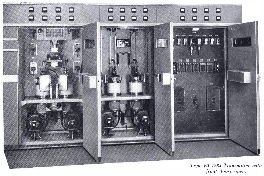
THE RADIO -FREQUENCY PANEL (left)

The radio-frequency unit which forms the left-hand cubicle of the transmitter is shown in the closeup view at the left. The first two r-f stages, which operate as harmonic generators, are mounted in a separate housing at the top of this unit. The four 813's form the IPA stage project from the bottom of this exciter housing. The RCA 889-R's which form the output stage are mounted in porcelain jackets through which air is blown by the blowers shown just beneath. This air is drawn from a "plenum chamber" in the rear. Just in front of the 889-R's may be seen the two sets of plates which form the neutralizing condensers. Motors mounted beneath the shelf provide the means of controlling the position of these plates from the front of the panel.

A noteworthy feature of this r-f unit is the use of motor drives which are coupled to the tuning elements of the resonant circuits. These motors are controlled from switches located on the front door of the r-f compartment. Close inspection will reveal the tuning indicators visible just above the respective motors on the main panel, and below the motors on the exciter unit. These indicators make possible the pre-tuning of the complete transmitter prior to the application of power.

photo RCA ET-7285 THE POWER OUTPUT PANEL (right)

The power amplifier plate tank circuit and harmonic attenuator are mounted on a panel insulated from the ground. The r-f return path to ground is supplied through a single by-pass condenser. This arrangement produces a circuit of high stability free from parasitics. The two r-f indicating instruments provide a visual check for balanced load currents. The output circuit feeds into a 600 ohm load balanced with respect to ground. High reactance filament transformers and the carrier monitor are mounted on top of the plenum chamber at the base of the unit. This carrier monitor is an "electronic watchman" which keeps constant vigilance over the transmitter output. Should the percentage of modulation or r-f carrier level drop below a specified level, the monitor provides the initiating action for ringing an alarm; or, in the case of dual transmitter operation, stop the "Main" unit and start up the "Stand-by" unit. Capacitively coupled to the PA plate tank circuit the monitor uses the picked energy to fire a thyratron which actuates a pilot relay. In case of (1) low or no modulation, (2) low or no carrier, or (3) failure of any of the monitor circuits, the transmitter in operation is shut down and the stand-by transmitter automatically put on the air.

photo RCA ET-7285 
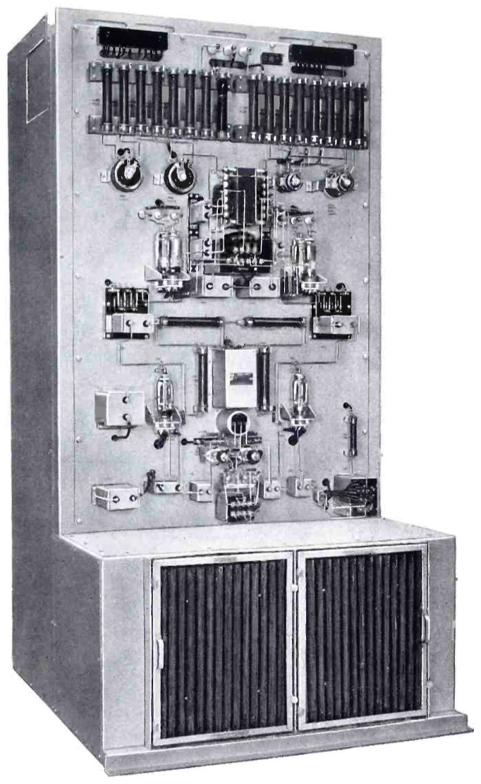
THE LOW POWER AUDIO PANEL (left)

The audio components of the ET-7285 Transmitter are mounted on the rear side of an inverted "T" frame which forms the center cubicle of the transmitter. The circuit employed is the same as that used so successfully in the RCA 5 and 50-E Broadcast Transmitters. All stages, including the modulator, are connected push-pull. The input stage (just above the shelf) is a pair of RCA 1613's; the second audio stage employs a pair, of RCA 828's; and the driver stage, four RCA 828's. The components of these stages are mounted in progressive fashion from bottom to top of this unit. All connections, except filament, are bus-bar. All terminals are in the clear and are plainly marked as are all components. The "vertical chassis" arrangement provides free air circulation and the accessibility of all parts makes for easy maintenance. A plenum chamber (bottom of the unit) supplies filtered air to the modulator tubes located on the front panel. An innovation in the ET-7285 Transmitter is the inverted channel at the top of the frame, which forms a wire duct. All interconnecting wiring between units runs in this channel and is connected into the three units through the terminal boards mounted at the top of the panels.

photo RCA ET-7285 
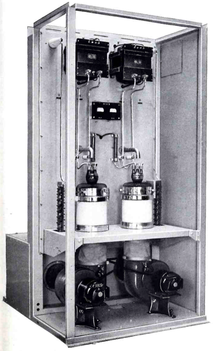
THE MODULATOR PANEL (right)

In the front part of the audio cubicle are located the two RCA 889-R's which function as a Class "B" modulator for the high-level modulated r-f power amplifier. These tubes, like the r-f amplifier tubes, are mounted in porcelain jackets through which air is forced by the blowers at the bottom of the unit. Tube protection from air failure is secured through the use of damper valves situated in the air stream. Mechanically coupled to mercury switches, these air-interlock devices prevent the application of any voltage to the tubes if proper cooling air is not available. Thermal protection incorporated in each blower motor serves to protect them from overheating or under voltage. The grid seals of the 889-R's are also cooled by a stream of air directed on them from above by small pipes. It is interesting to note that the use of 889-R's in both r-f amplifier and modulator reduces the number of tube types used and thereby simplifies maintenance of spares. High-reactance filament transformers mounted at the top of the panel limit the filament "starting" current to a safe value. The small panels at either side of the modulator tubes are the feedback "ladders."

photo RCA ET-7285 
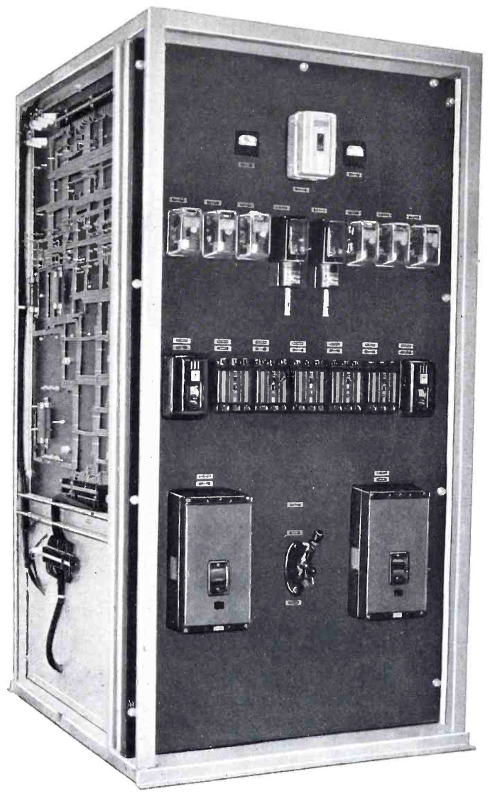
THE CONTROL PANEL (left)

The ebony-asbestos control panel shown at the left is located behind a non-interlocked door in the righthand cubicle of the transmitter. On this panel are mounted all circuit breakers and overload relays. Each circuit fed by the main power supply bus is provided with one of these circuit breakers to isolate it in case of overload or short circuit. Full vision, high-speed overload relays protect the power amplifier and modulator tubes, the rectifier and main line. The dead front switch located in the lower center is the Hi-Low power change switch. An electrically operated time switch encased in the light metal housing at the top of the panel automatically starts and stops the transmitter according to a preset schedule. Other control relays and contactors are mounted inside this unit on a panel, the rear of which may be seen at the left in this view. Through the action of these relays and contactors, automatic "sequence starting" and "3-cycle overload recycling" are provided. All of these relays are energized by a three-phase rectifier provided especially for this purpose.

photo RCA ET-7285 
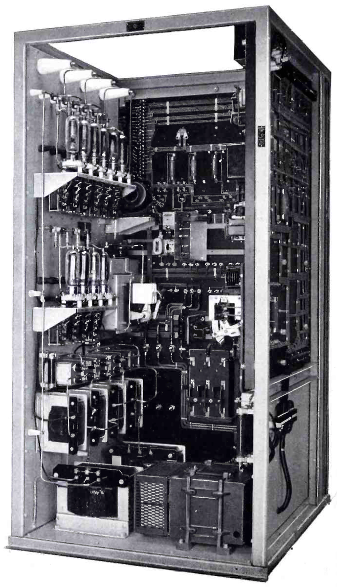
THE RECTIFIER UNIT (right)

The rear of the rectifier cubicle is shown in the view at right. A three-phase full-wave rectifier and a single-phase bridge-type rectifier are located near the top of the left-hand panel. A small blower located adjacent to this high -voltage rectifier supplies a temperature-controlled air-blast to the base of the RCA 872-A rectifier tubes. A thermostatically controlled heater element provides a warm blast for cold weather operation. Just below the blower may be seen the grounding switch which automatically grounds both high and low voltage filters when power is turned off. At the left of this switch unit is the low-voltage power supply unit consisting of four 872-A's in a single-phase full-wave circuit. This unit supplies plate voltage for all stages except the final r-f and the modulator. Grid biasing for all stages is provided by a selenium rectifier mounted on the right side of the cabinet (not visible in this view). All wiring in this power and control cubicle is of either "switchboard" or bus-bar type and all components are plainly marked. Thus, in case of failure, circuits are easily traced. A voltage stabilizer (on the floor of the unit) supplies voltage stabilized within ½ percent to all filaments, thereby insuring long tube life.

TUBE COMPLEMENT
RF stages AF stages and modulator Rectifiers
Number Type Number Type Number Type
2 889-R 2 889-R 10 872A
4 813 6 828

4 807 2 1613


THIS TYPE OF TRANSMITTER IS INSTALLED IN THE FOLLOWING COUNTRIES

ITU Country
ITU Country
flag USA USA USA