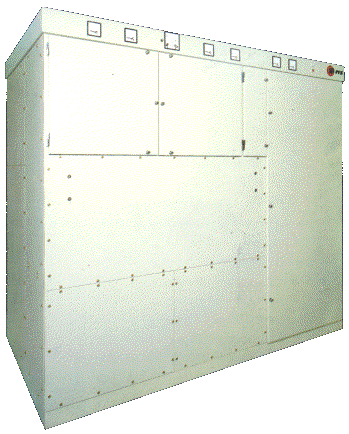
RIZ TRANSMITTERS OR 20 K-01/A

GENERAL DESCRIPTION


20 kW SW BROADCASTING TRANSMITTER TYPE RIZ OR 20 K-01/A

BASIC CHARACTERISTICS AND USES

photo RIZ Transmitters OR 20 K-01/A 20 kW Short Wave Broadcasting / Communication Transmitter type OR 20 K-01/A is a member of the RIZ's new generation of automatic tunable, amplitude modulated transmitter, capable to operate at any frequency within the SW frequency band between 3.2 and 18 MHz, output power up to 20 kW.

With completely solid state modulator, using Polyphase Pulse Duration Modulation, and a new approach for getting SSB signal this transmitter is superior to any other standard SW transmitter in the 20 kilowatt power range.

Using DSP (Digital Signal Procesing), modified Phase Shift method and some basic principles of Kahn System, an advanced SSB system is achieved and applied to C-class RF output amplifier, resulting in excellent transmitter efficiency.

This transmitter, as all other RIZ's transmitters, is designed in accordance with CCIR recommendations and the German ARD standards for this type of service.

The most modern tuning and sequential control based on 16-bit microcontroller, Programmable Logic Devices (PLD), effective transmitter management, as well as complete unattended remote operation, are achieved.

Multifunctional display menu enables monitoring of all relevant transmitter parameters. The major parameters are indicated separately on clearly visible analog instruments and signalization.

FEATURES

OR 20 K-01/A, is one of the new generation SW Broadcasting / Communication Transmitters, having the following major characteristics:

* Polyphase Pulse Duration Modulation

* operation at any frequency between 3.2 and 18 MHz

* automatic tuning

* up-to-date technology

* only one tube is used

* quick and simpe installation

* easy front and rear access

* minimised exploitation and maintenance costs

* reliable operation in extreme climatic and environmental conditions

* possibility of remote control and unattended operation.

CIRCUIT DESCRIPTION

The operation principle of the transmitter is shown on the Block Diagram. The unit Power Distribution ensures the necessary voltages and consists of:

Sequential Control ensures the connection between the operator with the executive components of the transmitter, either over the keyboard or over the remote control via RS 422 interface.

Sequential Power Control controls the ventilator and contactor operation.

Tuning Control ensures the automatic tuning of RF circuits over the complete frequency range.

The RF Synthesizer is performed as up-to-date direct digital synthesizer (DDS), which enables the digital control of amplitude, frequency and signal phase.

RF Driver is a 300W MOSFET amplifier supplied with necessary power supply and protection units.

AF Processor is of DSP technology construction. The input signal is digitalized, and after processing, the amplitude and phase components are generated. The amplitude component is led, via an opto-fiber, to the Solid State Modulator.

In the SSB mode operation, the phase component in digital form is led to the RF Synthesizer.

SOLID STATE ANODE MODULATOR

The anode modulator is constructed in solid state technology, which is of better efficiency, of more reliable operation and of better audio characteristics, in comparison to the tube-type modulators.

The anode modulator consists of 18 IGBT double stages, connected in series. Each supplies 2x500V. By switching-in or switching-off of some of the stages, the anode voltage from 0 to 18kV is obtained, thus enabling even 125% modulation.

The modulator is supplied by ±270VDC. It comprises 9 DC/AC converters, operating on the frequency of 25kHz. Each of the associated transformers Tr1 to Tr9 has 4 secondaries, which supply 500V AC signal each. Due to the operation at high frequency, the transformers are of small dimensions and weight, so that the modulator is lighter, if compared to the modulators designed with 50Hz transformers.

Between the outputs of certain IGBT Double Stages, the filter chokes are connected.

IGBT DOUBLE STAGE (2x500V)

This unit comprises two IGBT Stages connected in series and control board. The commands to switch-in a certain stage come over the two opto-fibers onto the Control Board.

Also, over the third opto-fiber, the possible failures are signalized, which makes the detection and repair considerably easier.

The 500V 25kHz voltage is rectified by the rapid rectifier and over the Protection IGBT led to the LC filter. The protection IGBT switches off the stage in case of the Switching IGBT break-through.

When Switching IGBT is ON 500VDC voltage from associated capacitor is connected in series with other stages.

The overcurrent of the modulator is controlled by the resistor connected between the two stages.

SOLID STATE UG2 MODULATOR

This unit enables the additional modulation of the screen grid. It consists of 4 G2 Double Stages connected in series and DC/AC converter with appropriate transformer.

G2 DOUBLE STAGE (2x200V)

The operation principle is identical to that of IGBT Double Stage in the anode modulator, except that this unit has no protection IGBT, as it is about the operation with the voltage of 200V, and the switching IGBT is less loaded.

POWER AMPLIFIER AND OUTPUT CIRCUIT

The drive signal comes over the wide-range transformer to the grid matching circuit. The coil is for the coarse tuning, while the fine tuning is performed over the vacuum variable capacitor. The tube 4CX20000B operates in the class C, with 7kV anode voltage. The double Π-filter matches the anode to 50 Ohm, and comprises the two coils for the coarse tuning and three vacuum variable capacitors for fine tuning. On the low frequencies, the actuator switches in the additional fixed vacuum capacitor. The TV filter suppresses additionally higher harmonics.

All variable coils and capacitors are driven by step motors, which shortens the necessary time (max. 30 sec.) and increases the tuning precision.

TECHNICAL SPECIFICATIONS
OPERATING CONDITIONS
Power Supply
Mains voltage 3 x 380V / 220V, +5%, -10%
Power consumption (fm=1kHz/m=1) 56 kVA
Mains frequency 50 Hz ±2Hz, or 60 Hz as option
Power factor cos phi greater than 0,9
Modulator Input
Input impedance (from 60 to 7500 Hz) 2000 Ohms balanced standard,
600 Ohms balanced, as option
Input level (for fm=1 kHz, m=1)
(0 dBm=0.775V across 600 Ohms)
-6 to +12 dBm
Transmitter Output
RF output load impedance 50 Ohms unbalanced
Permissible VSWR s less than 2
Climatic Conditions
Temperature in transmitter hall +5 to +45 C
Max. altitude above sea level 2300 m
Relative humidity less than 90%
ELECTRICAL CHARACTERISTICS
RF Output Power
Carrier power in the range 3.2 to 26.1 MHz 20 kW A1, 20 kW PEP SSB
Frequency range 3.2 to 18 MHz
Frequency stability 2 x 10⁻⁷ per day
Modulation principle Polyphase Pulse Duration Modulation
Type of emission AM, CW, SSB (with 6 dB / 12 dB carrier reduction below PEP), ISB (optional), F1 (optional), F6 (optional)
Modulation Characteristics
The ratio of input to output as function of modulation depth up to m=80% does not differ by more than ±0.5 dB
Intermodulation Distortion 35 dB relative to either of two equal test tones at full PEP
Signal to Noise Ratio
Unweighted more than 50 dB
Weighted more than 55 dB
Reference level m=100% fm=1 kHz,sinusoidal
Mains voltage sinusoidal
Harmonic and Spurious Emission
Harmonic and Spurious Emission more than 56 dB
Carrier Shift
Carrier shift at m=90% with fm=1 kHz sinusoidal and
at a constant mains voltage referred to the unmodulated carrier
less than 4%
Overall Efficiency
Overall efficiency more than 60% (fm=1kHz, sinusoidal)
Specifications may change without notice

TUBE COMPLEMENT
RF stages AF stages and modulator
Number Type Number Type
1 4CX20,000B


THIS TYPE OF TRANSMITTER IS INSTALLED IN THE FOLLOWING COUNTRIES

ITU Country
ITU Country