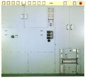
RIZ TRANSMITTERS OR 20 K-02

GENERAL DESCRIPTION


20 kW SHORT WAVE BROADCASTING TRANSMITTER TYPE RIZ OR 20 K-02

BASIC CHARACTERISTICS AND USE

photo RIZ Transmitters OR 20 K-02 Short Wave Broadcasting Transmitter Type RIZ OR 20 K-02 is a standard amplitude modulated transmitter, designed for operation at any frequency between 3.2 and 22 MHz, with carrier power of 20 kW.

It meets all CCIR recommendations for this type of service.

The transmitter is built as a self contained, compact and light-weight unit. Therefore, it is very suitable for installations in containers for fixed or transportable stations.

Advanced cabinet and functional layout provides good survey, easy accessibility to all components and minimum floor space requirements. All control and monitoring elements are placed on the front panel of the transmitter. The supervision of the transmitter is facilitated by the use of signal lamps indicating the operating status of the equipment.

The control and interlocking system of the transmitter is designed for easy connection to remote control and supervision circuits.

Particular attention has been paid to reliability. Only modern and highest quality components of current production are used. To minimize spares requirements the number of different components has been reduced to a minimum. The number of electron tubes has been minimized by using transistorized preamplifiers.

FEATURES

* use of only one tube type

* application of up-to-date technology

* quick and simplified installation

* full front and rear accessibility

* minimum floor space requirements

* minimized running and maintenance costs

* high reliability and remarkable stability of characteristics in extreme climatic and environmental conditions

* possibility of unattended operation

* possibility of remote control

* tuning to any frequency between 3.2 and 22 MHz

CIRCUIT DESCRIPTION

The transmitter consists basically of four sections as follows: RF Chain, AF Chain, Rectifiers and Protection and Control System.

RF CHAIN

Modern solid state technique is applied throughout. Only two tubes are used in the final stage - RF2.

RF 1 Stage

The RF signal generated in the crystal oscillator (or in a frequency synthesizer - as option) is amplified in the RF preamplifier followed by a wide-band amplifier capable to drive the final stage.

RF2 - Final Stage

In this stage two air-cooled ceramic tetrodes RS 2012 CL are connected in parallel and operate as a Class C power amplifier. The modulating AF signal delivered by the modulation transformer is applied to the anode circuit of the RF final stage through a modulation inductor.
Anode oscillating circuit of the final stage is designed as a double PI-filter network, offering excellent smoothing of harmonics as well as a flexible matching characteristics.

AF CHAIN

The AF chain is conventional consisting of a transistorized voltage amplifier AF1 which directly drives the AF2 final stage equipped with two air-cooled ceramic tetrodes.

AF1 Stage

Band-pass filter at the input determines the band-width of the radiated AF signal. Afterwards this signal is split and amplified in two separate channels to the level necessary to drive directly the final stage - AF2.

To improve the frequency response and to reduce the non-linear distortion, negative feedback is applied.

Use of the bias-compensation unit significantly improves the overall efficiency by reducing the quiescent currents of the modulator final stage to zero.

AF2 - Final Stage

This stage is equipped with two air-cooled ceramic tetrodes RS 2012 CL and operates as a push-pull Class B amplifier.

PROTECTION AND CONTROL SYSTEM

This system controls all phases of switching on procedure as well as the operation of the transmitter itself.

Switching-on procedure is carried out in five steps: None of the steps can begin if the previous one is not accomplished. Important currents and voltages are permanently supervised during the operation, and reaction to overcurrent, undervoltage and reflection is performed in an appropriate way.

Thus equipment and maintenance staff are fully protected.

The whole procedure of switching-on and the actual status of operation are indicated on the front panel.

RECTIFIERS

The high voltage rectifier and the other auxiliary rectifiers used in the transmitter for different DC supplies are all of semiconductor type. In order to ensure good ripple reduction and efficient operation these rectifiers operate in three-phase full wave configuration.

Rectified voltages and currents are supervised and monitored by supervision and protection units on the front instrument panel.

MECHANICAL CHARACTERISTICS

The transmitter is enhoused in a metal cabinet. The doors in front of the final stages enable easy access to final stage tubes.

The modular design of all low power stages and control system also facilitates maintenance.

The transmitter is air-cooled using a built-in blower.

The air intake is through a back side air filter while air outlet is above the final stage tubes.

OPERATING CHARACTERISTICS

Normal Operation

The transmitter is designed for continuous 24- hour operation with an average modulation depth of m=60% and peaks up to m=100%.

Test Operation

The transmitter is designed for test operation with a sinusoidal signal, frequency 1 kHz, and a modulation depth of 100% for a duration of 60 minutes.

Overmodulation

The transmitter can withstand, without damage, a short duration of AF input signal, fm = 1 kHz, 6 dB above the level required for 100% modulation.

Stability of Technical Data

The technical data stated in this specification are guaranteed for mains voltage tolerance between +5% to -10%, with the exception of RF output power, the consumed power, efficiency and carrier shift.

Change of Operating Frequency

Necessary frequency changes can be easily executed by operating staff within less than two minutes.

TECHNICAL SPECIFICATIONS
OPERATING CONDITIONS
Power Supply
Mains voltage 3 x 380 V / 220 V, +5%, -10%
Power input (fm=1kHz/m=1) 60 kVA
Mains frequency 50 Hz ±2 Hz
Power factor cos phi greater than 0.9
Modulator Input
Input impedance (from 60 to 10000 Hz) nominal 600 Ohms balanced
Input level (for fm=1 kHz, m=1)
(0 dBm=0,775 V across 600 Ohms)
-4 to +10 dBm
Transmitter Output
RF output load impedance 50 Ohms unbalanced
60 Ohms unbalanced on request
Permissible VSWR s less than 2
Climatic Conditions
Temperature in transmitter hall +5 to +45 C
Max. altitude above sea level 2000 m
Relative humidity less than 96%
ELECTRICAL CHARACTERISTICS
RF Output Power
Carrier power in the range 3.2 to 22 MHz 20 kW
RF Exciter
Crystal oscillator with fixed frequency in the range 3.2 to 22 MHz
Frequency precision and stability 2 x 10⁻⁶ Hz/day
Frequency synthesizer as option
Modulation System
Type of modulation High level amplitude modulation
Type of emission 20 A3
Bandwith limiting filters 4,5 kHz or 5 kHz available as option
Modulation Characteristics
The ratio of input to output as function of modulation depth (m=30 ... 80%) does not differ by more than ±0,5 dB
Signal to Noise Ratio
Unweighted more than 50 dB
Weighted more than 60 dB
Reference level m=100% fm=1 kHz, sinusoidal
Mains voltage sinusoidal
Spurious Emission
Mean power of any spurious emission supplied to the antenna transmission line below the mean power of the fundamental more than 60 dB
Carrier Shift
Carrier shift at m=90% with fm=1 kHz sinusoidal and
at a constant mains voltage referred to the unmodulated carrier
less than 4%
Overall Efficiency
Overall efficiency more than 43% (fm=1kHz, sinusoidal)
Specifications may change without notice

TUBE COMPLEMENT
RF stages AF stages and modulator
Number Type Number Type
2 RS 2012 CL 2 RS 2012 CL


THIS TYPE OF TRANSMITTER IS INSTALLED IN THE FOLLOWING COUNTRIES

ITU Country
ITU Country