STRETCHYMAN MKII

GENERAL DESCRIPTION

New for 2025, the 9G Communications 125W Shortwave Transmitter MKII.

photo Stretchyman MKII 
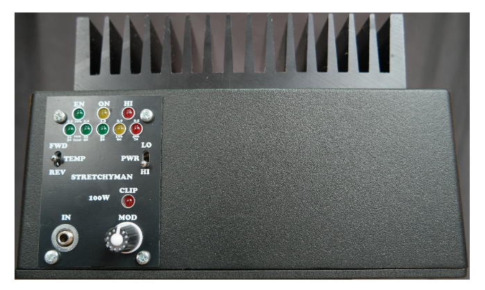
In 2016 I decided to design and build a portable, affordable and efficient 100W transmitter, it has been a long journey. This is the 2nd edition.

So, what have we got…

The design is based around a 4 FET Class E RF stage, highly efficient, hence the small size and light weight. New for 2025 are the use of the latest GaN FETs enabling increased efficiency and higher frequency operation (Currently 14MHz). The Modulator is PWM using the latest Half Bridge FET driver and SiC FETs. Voltages, SWR levels and Temperature are constantly monitored by a custom PIC controlled sequencer.

The design covers any single Broadcast Band; MW, 120m, 90m, 75m, 60m, 49m, 41m, 31m, 25m & 22m.

This design uses the latest devices from CREE (SiC) for the LF (below 7MHz) version and NEXPERIA (GaN) for the HF version. Having 4 devices means the design is more than capable of providing a 200W carrier but would need a higher voltage and this would take it over and above the what is generally regarded as the maximum safe voltage for humans of 48V. Remember 125W is just the carrier level and the output peaks at 500W PEP. This makes the transmitter incredibly rugged.

CHANGING FREQUENCY.

ALL designs have DIP switches and you will receive a table on what frequencies are programmed in. alternatively there is an ‘Oscillator’ version which gives improved frequency stability and a cleaner spectrum, this can be changed to any (in band) frequency. I would recommend this if you already have a fixed frequency license.

photo Stretchyman MKII OPERATION.

I’ve made this incredibly simple to avoid any issues. On the front panel there are 2 switches.

The Left Hand switch is FWD PWR (UP), TEMPERATURE (MID) and REV SWR (DOWN). In the UP position the 5 LEDs give a bargraph of relative output. In the down position ideally you will only have one (or two) LEDs lit indicating a low SWR of <1.2:1. If an amber LED is lit then the SWR will be over 2:1 and it would be wise to check your antenna.

The Right Hand switch is LOW POWER (UP), HIGH POWER (DOWN). The unit will ONLY start with the switch in the UP position. Power will be between (approx.) 5 & 10W. Whilst this can be used for lower power broadcasting its primary use is to check the antenna SWR.

REMOTE OPERATION.

Due to many requests remote operation is now available by moving a link on the rear of the front panel PCB. This merely bypasses the need to change the position of the right hand switch which must be left in the UP position.

SEQUENCED START UP.

With the RH switch in the correct (UP) position, apply power (48V) to the unit, observing polarity, you should here the internal relay chatter and the TOP ROW of LEDs should have GREEN (ENABLE) and AMBER (5V LOGIC OK) LEDs lit. The bargraph will have one or two LEDs lit. The unit will now be transmitting in LOW POWER mode. Check the SWR by flipping the LH switch down (or use an external SWR meter), if ALL is good then flip the RH switch down to HIGH POWER mode. You are now transmitting a 125W carrier.

AUDIO INPUT AND MODULATION LEVEL.

It’s IMPORTANT for any A.M. transmitter to have the optimum level of audio so the carrier if fully modulated to 100%. This means that the carrier will dip to zero and to twice the carrier level (X4 power) when 100% is achieved. If the audio is too LOUD! Then clipping will occur and the signal will sound distorted. How do you measure this? Ideally with a ‘Scope but I have fitted a front panel LED to show you when that level is achieved. With the audio pot CCW apply the audio and rotate the pot CW until the LED just starts to blink, this is the optimum level for 100% modulation. You will need 1V RMS (approx. line level) for full modulation. This can be balanced or unbalanced. As with all program material the levels should NEVER exceed a maximum value, this is called LIMITING and must be done externally and should also be COMPRESSED to make it sound LOUD! Some research is best done to understand these terms as the quality of the audio is VERY IMPORTANT!

The audio I/P is BALANCED, if using an unbalanced source only wire the tip of the stereo jack & gnd, leave the sleeve (middle connection)OPEN, DO NOT insert a MONO jack as this will give poor audio.

photo Stretchyman MKII HARDWARE & PROTECTION.

The unit has two internal fuses. 600mA and 7A.

Voltages are monitored internally and if the voltage ever exceeds 54V the unit will shut down and blink the second LED in the bargraph = OVLO. If the internal 12V ever drops below 11V then the third LED will blink = UVLO. ANY SWR event will blink the final RED LED in the bargraph. The unit will SHUT DOWN if ANY of these events occur. At startup if the voltage is >54V the first GREEN led will light but the unit will NOT enable (you will not hear the relay chatter and the EN GREEN led will not light). If the transmitter suddenly operates into a dead short it will either disable itself or blow a fuse. The transmitter is fully protected. You have nothing to worry about!

ALL units have been designed and are hand built by myself. I take great pride in my work and can assure you there’s nothing else like it and I hope it goes on to provide you with many years of trouble free service.

I have 50 or so similar units that are in operation around the globe from Chile to Australia and have never had any issues. Some units are in constant operation 24/7.

I offer 3 year guarantee.

OK I think that’s it from me, just to say thanks again for your interest in my product.

Stretchyman MKII block diagram
TUBE COMPLEMENT
RF stages AF stages and modulator
Number Type Number Type
- - - -


THIS TYPE OF TRANSMITTER IS INSTALLED IN THE FOLLOWING COUNTRIES

ITU Country
ITU Country
flag AUS AUS AUSTRALIA flag FIN FIN FINLAND