| GENERAL DESCRIPTION |
 High quality design for best reliability
| TECHNICAL SPECIFICATIONS | |
| Type of transmission | A3E AM (incl. DCC) H3E SSB R3E SSB According to the ITU Radio Regulations, Geneva 1990, Article 4. |
| Frequency range | 5.95 - 26.1 MHz (standard) 3.9 - 26.1 MHz (optional) Broadcasting bands according to the ITU Radio Regulations, Geneva 1990. |
| Rated carrier output power | 500 kW into a matched 300 Ohms balanced load or a 50 Ohms unbalanced load. |
| Frequency stability | Determined by oscillator or synthesizer used, which is normally equal to or better than CCIR requirements. |
| Radio frequency input level | 1 Vrms into 50 Ohms |
| Radio frequency output impedance | 50 Ohms unbalanced (standard) 300 Ohms balanced (optional) |
| Maximum permissible VSWR | 2.0 at 50 Ohms unbalanced 1.7 at 300 Ohms balanced |
| Radio-frequency harmonics and spurious radiation | According to the ITU Radio Regulations, Geneva 1990, appendix 8, column B, measured at the transmitter output with a correctly matched load. |
| Carrier-voltage shift | less than 5% for instantaneous application or removal of 95% sine wave modulation at 1 kHz, with constant mains voltage. |
| Type of modulation | High-level anode modulation |
| Audio-frequency input level | 0 dBm to 20 dBm into 600 Ohms balanced, for 100% modulation. |
| Audio-frequency response | ±1 dB 50 Hz - 7'500 Hz referred to 70% modulation at 1'000 Hz |
| Audio-frequency distortion | Less than 3.5% 50 Hz - 7'500 Hz related to AF input signal at the TSM amplifier for m = 0.3 - 0.9 Less than 1.0% with an adaptive non-linear compensator (optional) |
| Modulation capability Program material Tone tests |
50 Hz - 7'500 Hz continuous (with peaks up to 100% related to the input) 50 Hz - 7'500 Hz m = 1 during 10'/h, m = 0.75 continuous 1'000 Hz 1 h continuous Related to AF input signal at the TSM amplifier (sine wave, DSB). |
| Hum and noise level | Less than -60 dB RMS, unweighted according to CCIR Rec. 468-3 1990, Annex II. Referred to 100% modulation at 1'000 Hz sine wave |
| Mains supply 50 or 60 Hz | Low voltage 400 V, 3-phase and neutral For tolerances up to ±10% an optional 400 V voltage regulator is available for the auxiliary supplies. High voltage 3 - 24 kV, 3-phase Permissible voltage tolerance ±5% Permissible frequency tolerance ±2 Hz |
| Maximum theoretical power consumption | Low voltage 46 kVA High voltage 1'007 kVA Total 1'053 kVA For 100% sinusoidal modulation (actual power consumption is lower during program operation). |
| Power factor for equipment | More than 0.95 with 100% modulation at 1'000 Hz |
| Overall efficiency | Min. guaranteed more than 75% Typically more than 77% With standard cooling at 0 - 100% modulation |
| Frequency change time | 30 seconds max. |
| Ambient temperature | 1°C - 45°C |
| Maximum humidity | 95% |
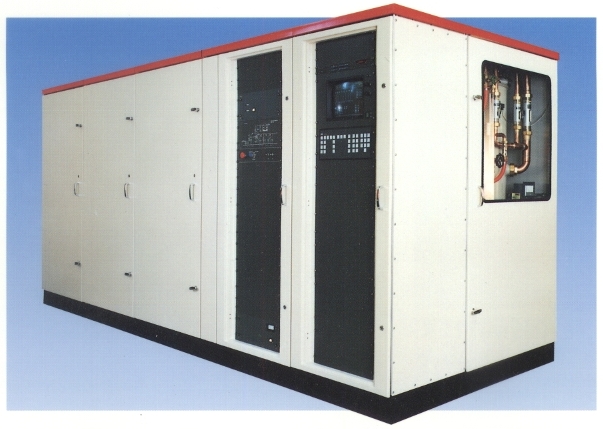
| Dimensions Transmitter TSM |
length 4.80 m width 1.60 m height 2.10 m length 3.25 m width 1.30 m height 2.00 m |
| Specifications may change without notice | |
| TUBE COMPLEMENT | |||
| RF stages | AF stages and modulator | ||
| Number | Type | Number | Type |
| 1 | TH576 | ||
| 1 | CTK 12-1 | ||
| THIS TYPE OF TRANSMITTER IS INSTALLED IN THE FOLLOWING COUNTRIES | |||||
| ITU | Country | ITU | Country | ||
| CHN | CHINA | EGY | EGYPT | ||
| LBY | LIBYA | ARS | SAUDI ARABIA | ||
| TUN | TUNISIA | CVA | VATICAN CITY | ||